Toyota Venza: Components
COMPONENTS
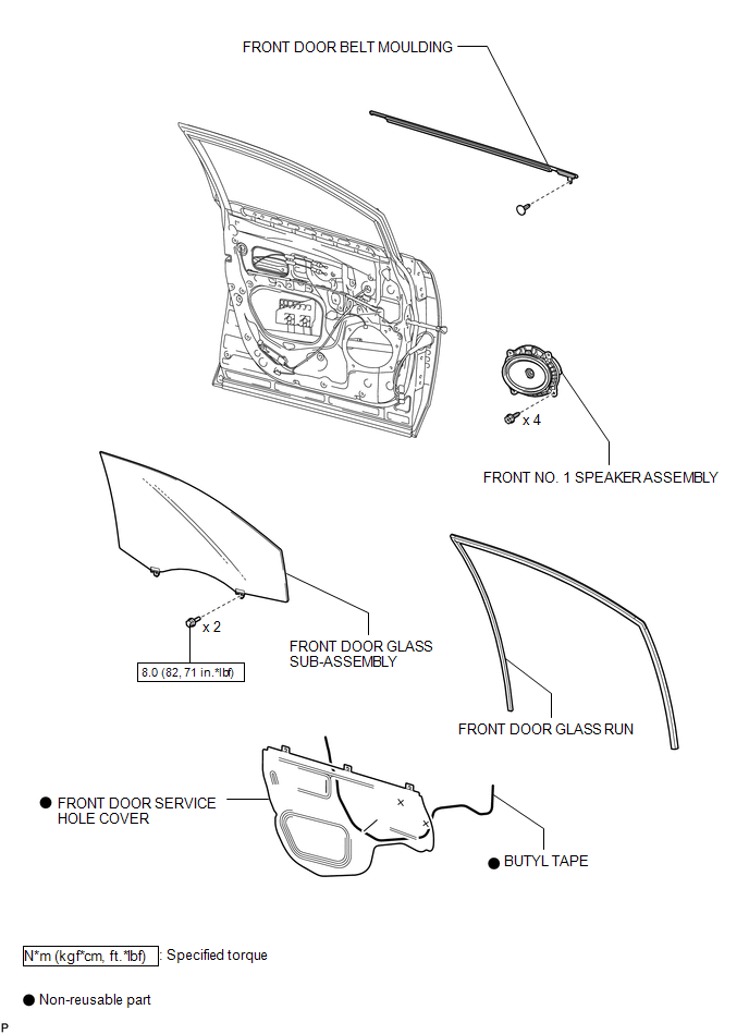
ILLUSTRATION
.png)
ILLUSTRATION

 Installation
INSTALLATION
PROCEDURE
1. INSTALL FRONT DOOR BELT MOULDING
(a) Engage the 5 claws to install the front door belt moulding.
(b) Install the ...
Other materials about Toyota Venza:
Dtc Check / Clear
DTC CHECK / CLEAR
1. CHECK DTCS
(a) Turn the engine switch off.
(b) Connect the Techstream to the DLC3.
(c) Turn the engine switch on (IG).
(d) Turn the Techstream on.
(e) Check for DTCs. Enter the following menus: Body Electrical / Smart Key /
Trouble ...
Inside Vehicle
General Maintenance
GENERAL MAINTENANCE
CAUTION / NOTICE / HINT
These are maintenance and inspection items that are considered to be
the owner's responsibility.
The owner can do them or they can have them done at a service center.
The ...
Panel Switches do not Function
PROCEDURE
1.
CHECK PANEL SWITCH
(a) Check for foreign matter around the switches that might prevent operation.
OK:
No foreign matter is found.
NG
REMOVE ANY FOREIGN MATTER FOUND
...

0.1679