Toyota Venza: Installation
INSTALLATION
PROCEDURE
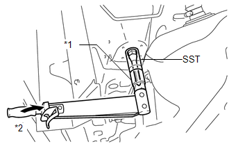
1. INSTALL STUD BOLT (for LH Side)
|
(a) Using SST and a socket wrench (21 mm), install the stud bolt. Text in Illustration
SST: 09817-33190 Torque: 180 N·m {1839 kgf·cm, 133 ft·lbf} |
|
2. INSTALL STUD BOLT (for RH Side)
HINT:
Perform the same procedure as the LH side.
3. TEMPORARILY TIGHTEN REAR NO. 2 BODY MOUNTING BRACKET SUB-ASSEMBLY LH
|
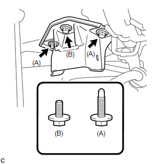
(a) Temporarily install the rear No. 2 body mounting bracket sub-assembly LH with the 2 bolts (A) and bolt (B). NOTICE: Two types of bolts are used. Install each bolt to the correct position. |
|
4. TEMPORARILY TIGHTEN REAR NO. 2 BODY MOUNTING BRACKET SUB-ASSEMBLY RH
HINT:
Perform the same procedure as the LH side.
5. INSTALL HOLE PLUG
(a) Install the 6 hole plugs.
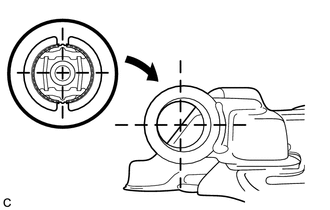
6. INSTALL REAR SUSPENSION MEMBER BODY MOUNTING FRONT CUSHION (for LH Side)
|
(a) Temporarily install a new rear suspension member body mounting front cushion while confirming the installation direction. |
|
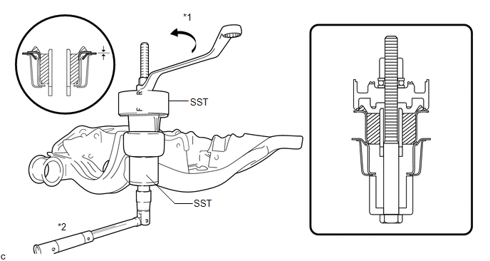
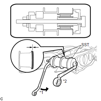
(b) Using SST, install the rear suspension member body mounting front cushion until there is no clearance between the suspension member sub- assembly and the rear suspension member body mounting front cushion.
 Text in Illustration
|
*1 |
Turn |
*2 |
Hold |
SST: 09830-10010
09830-01010
09830-01020
09830-01030
09830-01060
NOTICE:
- Tighten SST slowly and evenly.
- Apply a small amount of grease to the threads of SST (center bolt) before use.
- Install the side marked "F" of SST to the body mounting cushion.
7. INSTALL REAR SUSPENSION MEMBER BODY MOUNTING FRONT CUSHION (for RH Side)
HINT:
Perform the same procedure as the LH side.
8. INSTALL REAR SUSPENSION MEMBER BODY MOUNTING REAR CUSHION (for LH Side)
|
(a) Temporarily install a new rear suspension member body mounting rear cushion while confirming the installation direction. |
|
|
(b) Using SST, install the rear suspension member rear body mounting cushion until there is no clearance between the suspension member sub-assembly and the rear suspension member body mounting rear cushion. Text in Illustration
SST: 09830-36010 SST: 09515-21010 NOTICE:
|
|
9. INSTALL REAR SUSPENSION MEMBER BODY MOUNTING REAR CUSHION (for RH Side)
HINT:
Perform the same procedure as the LH side.
10. INSTALL REAR NO. 1 DIFFERENTIAL MOUNT CUSHION
.gif)
11. INSTALL REAR NO. 2 DIFFERENTIAL MOUNT CUSHION
12. TEMPORARILY TIGHTEN REAR DIFFERENTIAL CARRIER ASSEMBLY WITH DIFFERENTIAL SUPPORT
13. FULLY TIGHTEN REAR DIFFERENTIAL CARRIER ASSEMBLY WITH DIFFERENTIAL SUPPORT
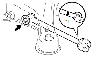
14. INSTALL REAR NO. 1 SUSPENSION ARM ASSEMBLY LH
|
(a) Temporarily install the rear No. 1 suspension arm assembly LH to the rear suspension member with the bolt and the nut. Text in Illustration
NOTICE:
|
|
|
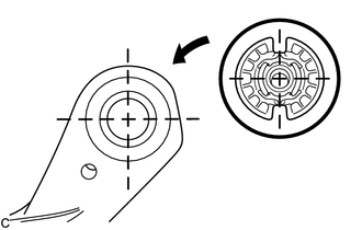
(b) Set the rear No. 1 suspension arm assembly LH in the tightening position shown in the illustration. Standard angle (A): 7°36' (7.6°) Standard length (B): 49.7 mm (1.96 in.) |
|
.png)
|
(c) Fully tighten the bolt in the tightening position. Torque: 80 N·m {816 kgf·cm, 59 ft·lbf} NOTICE: Since a stopper nut is used, temporarily tighten the bolt. |
|

15. INSTALL REAR NO. 1 SUSPENSION ARM ASSEMBLY RH
HINT:
Perform the same procedure as the LH side.
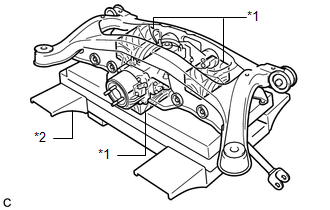
16. TEMPORARILY TIGHTEN REAR SUSPENSION MEMBER
|
(a) Support the rear suspension member using a jack and 3 wooden blocks as shown in the illustration. Text in Illustration
NOTICE: Support the rear suspension member until retightening of the suspension member is complete. HINT: Use properly sized wooden blocks to keep the jack and suspension member level. |
|
(b) Raise the rear suspension member using a jack with wooden blocks.
NOTICE:
When raising the rear suspension member, be careful not to damage the vehicle body or other components installed on the vehicle.
(c) Temporarily install the rear suspension member, 2 rear upper suspension member stoppers and rear lower suspension member stopper retainers with the 2 nuts (A), 2 nuts (B) and 2 bolts.
.png)
NOTICE:
Be sure to install the rear suspension member with the rear upper suspension member stoppers and the rear lower suspension member stopper retainers in the correct direction shown in the illustration.
(d) Fully tighten the 2 nuts (A).
Torque:
115 N·m {1173 kgf·cm, 85 ft·lbf}
HINT:
Fully tighten the nut (B) after fully tightening the rear No. 2 body mounting bracket sub-assembly in the following steps.
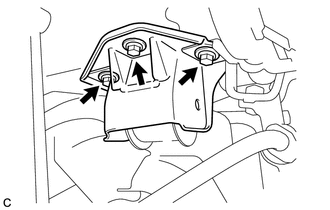
17. FULLY TIGHTEN REAR NO. 2 BODY MOUNTING BRACKET SUB-ASSEMBLY LH
(a) Lightly shake the rear suspension member to settle the body mounting cushion in the rear No. 2 body mounting bracket sub-assembly.
|
(b) Fully tighten the 3 bolts. Torque: 90 N·m {918 kgf·cm, 66 ft·lbf} |
|
18. FULLY TIGHTEN REAR NO. 2 BODY MOUNTING BRACKET SUB-ASSEMBLY RH
HINT:
Perform the same procedure as the LH side.
19. FULLY TIGHTEN REAR SUSPENSION MEMBER
|
(a) Using SST and a socket wrench (19 mm), fully tighten the 2 nuts. Text in Illustration
SST: 09961-00950 Torque: Specified Tightening Torque : 96 N·m {979 kgf·cm, 71 ft·lbf} NOTICE: This torque value is effective when SST is parallel to the torque wrench. HINT:
|
|
.png)
20. INSTALL FRAME WIRE
(a) Engage the 6 clamps, connect the connector and the hose to install the frame wire.
.png)
NOTICE:
Do not twist the frame wire when installing it.
21. INSTALL NO. 3 FLOOR WIRE (w/ HID Headlight System)
|
(a) Engage the clamp to install the No. 3 floor wire. NOTICE: Do not twist the No. 3 floor wire when installing it. |
|
.png)
22. INSTALL REAR DRIVE SHAFT SNAP RING LH
23. INSTALL REAR DRIVE SHAFT ASSEMBLY LH
24. INSTALL REAR DRIVE SHAFT SNAP RING RH
HINT:
Perform the same procedure as the LH side.
25. INSTALL REAR DRIVE SHAFT ASSEMBLY RH
HINT:
Perform the same procedure as the LH side.
26. ADD DIFFERENTIAL OIL
27. INSTALL REAR DIFFERENTIAL CARRIER COVER PLUG
28. CONNECT REAR NO. 1 SUSPENSION ARM ASSEMBLY LH
29. CONNECT REAR NO. 1 SUSPENSION ARM ASSEMBLY RH
30. TEMPORARILY TIGHTEN REAR NO. 2 SUSPENSION ARM ASSEMBLY LH
31. TEMPORARILY TIGHTEN REAR NO. 2 SUSPENSION ARM ASSEMBLY RH
32. INSTALL REAR STRUT ROD ASSEMBLY LH
33. INSTALL REAR STRUT ROD ASSEMBLY RH
HINT:
Perform the same procedure as the LH side.
34. INSTALL REAR HEIGHT CONTROL SENSOR SUB-ASSEMBLY (w/ HID Headlight System)
35. INSTALL NO. 3 PARKING BRAKE CABLE ASSEMBLY
|
(a) Install the No. 3 parking brake cable assembly with the bolt. Torque: 6.0 N·m {61 kgf·cm, 53 in·lbf} |
|
.png)
|
(b) Install the No. 3 parking brake cable assembly with the 2 nuts. Torque: 6.0 N·m {61 kgf·cm, 53 in·lbf} |
|
.png)
36. INSTALL NO. 2 PARKING BRAKE CABLE ASSEMBLY
HINT:
Perform the same procedure as the No. 3 parking brake cable assembly.
37. INSTALL REAR AXLE SHAFT NUT LH
38. INSTALL REAR AXLE SHAFT NUT RH
HINT:
Perform the same procedure as the LH side.
39. INSTALL REAR SPEED SENSOR LH
|
(a) Install the rear speed sensor LH to the rear shock absorber with coil spring with the bolt. Torque: 8.0 N·m {82 kgf·cm, 71 in·lbf} NOTICE: Do not twist the rear speed sensor wire when installing it. |
|
.png)
|
(b) Install the rear speed sensor LH to the rear axle carrier sub-assembly with the bolt. Torque: 8.5 N·m {87 kgf·cm, 75 in·lbf} NOTICE:
|
|
.png)
40. INSTALL REAR SPEED SENSOR RH
HINT:
Perform the same procedure as the LH side.
41. TEMPORARILY TIGHTEN PROPELLER WITH CENTER BEARING SHAFT ASSEMBLY
42. FULLY TIGHTEN PROPELLER WITH CENTER BEARING SHAFT ASSEMBLY
43. INSTALL NO. 1 FLOOR UNDER COVER
44. INSPECT AND ADJUST TRANSFER OIL
(a) Inspect and adjust the transfer oil (See page
).
45. INSTALL CENTER EXHAUST PIPE ASSEMBLY
(a) Install the center exhaust pipe assembly.
HINT:
Refer to the instructions for Installation of the exhaust pipe (See page
for 2GR-FE,
for 1AR-FE).
46. INSPECT FOR EXHAUST GAS LEAK
47. INSTALL REAR WHEELS
Torque:
103 N·m {1050 kgf·cm, 76 ft·lbf}
48. STABILIZE SUSPENSION
49. FULLY TIGHTEN REAR NO. 2 SUSPENSION ARM ASSEMBLY LH
50. FULLY TIGHTEN REAR NO. 2 SUSPENSION ARM ASSEMBLY RH
51. INSPECT AND ADJUST REAR WHEEL ALIGNMENT
(a) Inspect and adjust the rear wheel alignment (See page
).
52. CHECK FOR SPEED SENSOR SIGNAL
(a) Check for the speed sensor signal (See page
).
53. HEIGHT CONTROL SENSOR SIGNAL INITIALIZATION (w/ HID Headlight System)
(a) Initialize the height control sensor signal (See page
).
54. INSPECT AND ADJUST HEADLIGHT AIMING (w/ HID Headlight System)
(a) Inspect and adjust the headlight aiming (See page
).
 Removal
REMOVAL
PROCEDURE
1. REMOVE REAR WHEELS
2. REMOVE CENTER EXHAUST PIPE ASSEMBLY
(a) Remove the center exhaust pipe assembly.
HINT:
Refer to the instructions for Removal of the exhaust pipe (See p ...

Other materials about Toyota Venza:
System Diagram
SYSTEM DIAGRAM
Communication Table
Sender
Receiver
Signal
Communication Method
Main Body ECU (Driver Side Junction Block Assembly)
Combination Meter Assembly
Driver side door ...
Back Door Closer Operation Malfunction (B2250)
DESCRIPTION
The power back door ECU (power back door motor unit)*1 or back door closer ECU
(multiplex network door ECU)*2 receives signals from the latch switch, sector switch
and back door courtesy switch, which are built into the back door lock. Based o ...
HL AutoLeveling ECU Failure (B2420)
DESCRIPTION
When the headlight leveling ECU assembly detects a malfunction in itself, this
DTC is stored.
DTC No.
DTC Detecting Condition
Trouble Area
B2420
Malfunction of headlight leveling ECU ...

0.1604