Toyota Venza: Installation
INSTALLATION
PROCEDURE
1. INSTALL REAR NO. 1 SUSPENSION ARM ASSEMBLY LH
|
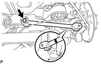
(a) Temporarily install the rear No. 1 suspension arm assembly LH to the rear suspension member with the bolt and the nut. Text in Illustration
NOTICE:
|
|
|
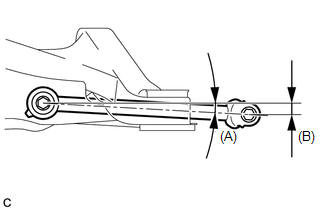
(b) Set the rear No. 1 suspension arm assembly LH in the tightening position shown in the illustration. Standard angle (A): 7°36' (7.6°) Standard length (B): 49.7 mm (1.96 in.) |
|
|
(c) Fully tighten the bolt in the tightening position. Torque: 80 N·m {816 kgf·cm, 59 ft·lbf} NOTICE: Since a stopper nut is used, fully tighten the bolt. |
|
2. INSTALL REAR NO. 1 SUSPENSION ARM ASSEMBLY RH
HINT:
Perform the same procedure as the LH side.
3. INSTALL REAR SUSPENSION MEMBER
(a) Raise the rear suspension member with a jack.
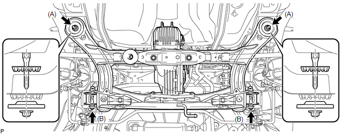
(b) Temporarily install the rear suspension member, 2 rear upper suspension member stoppers and 2 rear lower suspension member stopper retainers with the 4 nuts and 2 bolts.
NOTICE:
Be sure to install the rear suspension member with the rear upper suspension member stopper and the rear lower suspension member stopper retainer in the correct direction as shown in the illustration.
(c) Fully tighten the 2 nuts (A).
Torque:
115 N·m {1173 kgf·cm, 85 ft·lbf}
|
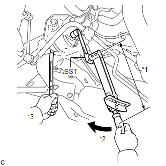
(d) Using SST and a socket wrench (19 mm), fully tighten the 2 nuts (B). Text in Illustration
SST: 09961-00950 Torque: Specified Tightening Torque : 96 N·m {979 kgf·cm, 71 ft·lbf} NOTICE: This torque value is effective when SST is parallel to the torque wrench. HINT:
|
|
4. CONNECT REAR NO. 1 SUSPENSION ARM ASSEMBLY LH
|
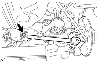
(a) Connect the rear No. 1 suspension arm assembly LH to the rear axle carrier sub-assembly LH with the bolt and the nut. Torque: 112 N·m {1142 kgf·cm, 83 ft·lbf} NOTICE: Since a stopper nut is used, temporarily tighten the bolt. |
|
5. CONNECT REAR NO. 1 SUSPENSION ARM ASSEMBLY RH
HINT:
Perform the same procedure as the LH side.
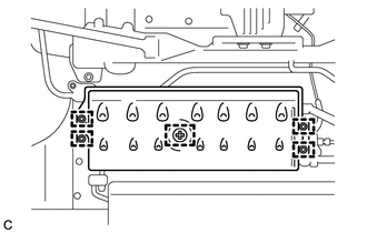
6. INSTALL FRAME WIRE
|
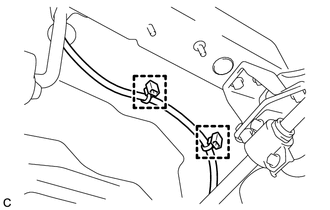
(a) Engage the 2 clamps to install the frame wire. NOTICE: Do not twist the frame wire when installing it. |
|
7. INSTALL NO. 3 FLOOR WIRE (w/ HID Headlight System)
|
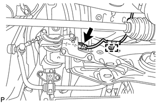
(a) Engage the clamp and connect the connector to install the No. 3 floor wire. NOTICE: Do not twist the No. 3 floor wire when installing it. |
|
8. INSTALL NO. 1 FLOOR UNDER COVER
|
(a) Install the No. 1 floor under cover with the 5 clips. |
|
9. TEMPORARILY TIGHTEN REAR NO. 2 SUSPENSION ARM ASSEMBLY LH
|
(a) Temporarily tighten the rear No. 2 suspension arm assembly LH to the rear suspension member with the rear suspension toe adjust cam sub-assembly, the No. 2 camber adjust cam and the nut (B). Text in Illustration
NOTICE: Ensure that the identification mark faces the rear side of the vehicle. HINT: When temporarily tightening the nut, keep the rear suspension toe adjust cam sub-assembly from rotating. |
|
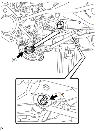
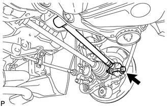
(b) Fully tighten the rear No. 2 suspension arm assembly LH to the rear axle carrier sub-assembly LH with the bolt (A) and the nut.
Torque:
112 N·m {1142 kgf·cm, 83 ft·lbf}
NOTICE:
Since a stopper nut is used, fully tighten the bolt.
10. TEMPORARILY TIGHTEN REAR NO. 2 SUSPENSION ARM ASSEMBLY RH
HINT:
Perform the same procedure as the LH side.
11. CONNECT REAR HEIGHT CONTROL SENSOR SUB-ASSEMBLY (w/ HID Headlight System)
|
(a) Connect the rear height control sensor sub-assembly to the rear No. 2 suspension arm assembly RH with the nut. Torque: 5.4 N·m {55 kgf·cm, 48 in·lbf} |
|
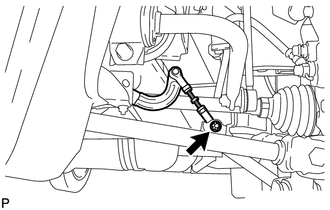
12. INSTALL REAR STRUT ROD ASSEMBLY LH
.gif)
13. INSTALL REAR STRUT ROD ASSEMBLY RH
HINT:
Perform the same procedure as the LH side.
14. INSTALL NO. 3 PARKING BRAKE CABLE ASSEMBLY
15. INSTALL NO. 2 PARKING BRAKE CABLE ASSEMBLY
16. TEMPORARILY TIGHTEN PROPELLER WITH CENTER BEARING SHAFT ASSEMBLY
17. FULLY TIGHTEN PROPELLER WITH CENTER BEARING SHAFT ASSEMBLY
18. INSPECT AND ADJUST TRANSFER OIL
(a) Inspect and adjust the transfer oil (See page
).
19. INSTALL CENTER EXHAUST PIPE ASSEMBLY
(a) Install the center exhaust pipe assembly.
HINT:
Refer to the instructions for Installation of the exhaust pipe (See page
for 2GR-FE,
for 1AR-FE).
20. INSPECT FOR EXHAUST GAS LEAK
21. INSTALL REAR WHEELS
Torque:
103 N·m {1050 kgf·cm, 76 ft·lbf}
22. STABILIZE SUSPENSION
(a) Lower the vehicle to the ground.
(b) Bounce the vehicle up and down at the corners to stabilize the rear suspension.
23. FULLY TIGHTEN REAR NO. 2 SUSPENSION ARM ASSEMBLY LH
|
(a) Align the matchmarks on the adjust cams and rear suspension member sub-assembly. Text in Illustration
|
|
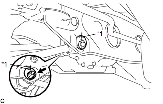
(b) Fully tighten the nut.
Torque:
100 N·m {1020 kgf·cm, 74 ft·lbf}
NOTICE:
The final torque must be applied under standard vehicle height conditions.
HINT:
When fully tightening the nut, keep the rear suspension toe adjust cam sub-assembly from rotating.
24. FULLY TIGHTEN REAR NO. 2 SUSPENSION ARM ASSEMBLY RH
HINT:
Perform the same procedure as the LH side.
25. INSPECT AND ADJUST REAR WHEEL ALIGNMENT
(a) Inspect and adjust the rear wheel alignment (See page
).
26. HEIGHT CONTROL SENSOR SIGNAL INITIALIZATION (w/ HID Headlight System)
(a) Initialize the height control sensor signal (See page
).
27. INSPECT AND ADJUST HEADLIGHT AIMING (w/ HID Headlight System)
(a) Inspect and adjust the headlight aiming (See page
).
 Components
COMPONENTS
ILLUSTRATION
ILLUSTRATION
ILLUSTRATION
...
 Removal
REMOVAL
PROCEDURE
1. REMOVE REAR WHEELS
2. REMOVE CENTER EXHAUST PIPE ASSEMBLY
(a) Remove the center exhaust pipe assembly.
HINT:
Refer to the instructions for Removal of the exhaust pipe (See p ...
Other materials about Toyota Venza:
Reporting safety defects for U.S. owners
If you believe that your vehicle has a defect which could cause a crash or could
cause injury or death, you should immediately inform the National Highway Traffic
Safety Administration (NHTSA) in addition to notifying Toyota Motor Sales, U.S.A.,
Inc.
(T ...
Inspection
INSPECTION
PROCEDURE
1. INSPECT DRIVE MONITOR SWITCH
(a) Measure the resistance according to the value(s) in the table below.
Standard Resistance:
Tester Connection
Switch Condition
Specif ...
Operation Check
OPERATION CHECK
1. CHECK NAVIGATION SYSTEM NORMAL CONDITION
(a) If the symptom is applicable to any of the following, it is intended behavior,
and not a malfunction.
Symptom
Answer
A longer route than expected is cho ...

0.1194