Toyota Venza: Components
COMPONENTS
ILLUSTRATION
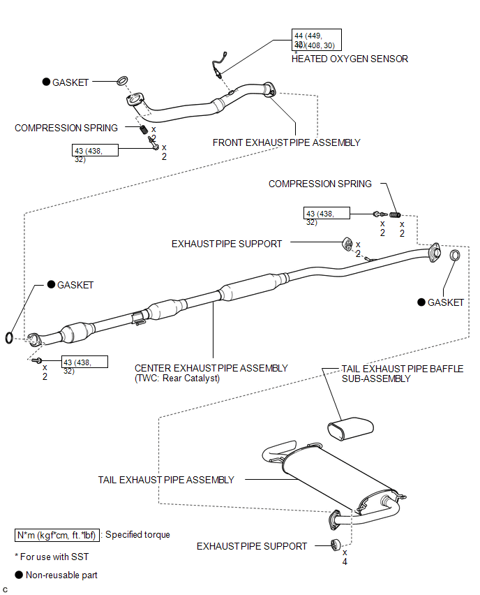
 Exhaust Pipe
...
 Installation
INSTALLATION
PROCEDURE
1. INSTALL HEATED OXYGEN SENSOR
2. INSTALL FRONT EXHAUST PIPE ASSEMBLY
(a) Using a vernier caliper, measure the free length of the compression
springs.
...
Other materials about Toyota Venza:
Entire Combination Meter does not Operate
DESCRIPTION
This circuit is the power source circuit for the meter. This circuit provides
two types of power sources; one is a constant power source mainly used as a backup
power source, and the other is an IG power source mainly used for signal transmiss ...
Terminals Of Ecu
TERMINALS OF ECU
1. TERMINALS OF ECU
Text in Illustration
*1
Component without harness connected
(Brake Actuator (Skid Control ECU))
Terminal No. (Symbol)
Terminal Description
1 (GND ...
Pressure Control Solenoid "D" Performance (Shift Solenoid Valve SLT) (P2714)
SYSTEM DESCRIPTION
The linear solenoid valve (SLT) controls the transmission line pressure for smooth
transmission operation based on signals from the throttle position sensor and the
vehicle speed sensor. The TCM adjusts the current to SLT solenoid valve ...

0.1671