Toyota Venza: Brake Signal Malfunction (B2284)
DESCRIPTION
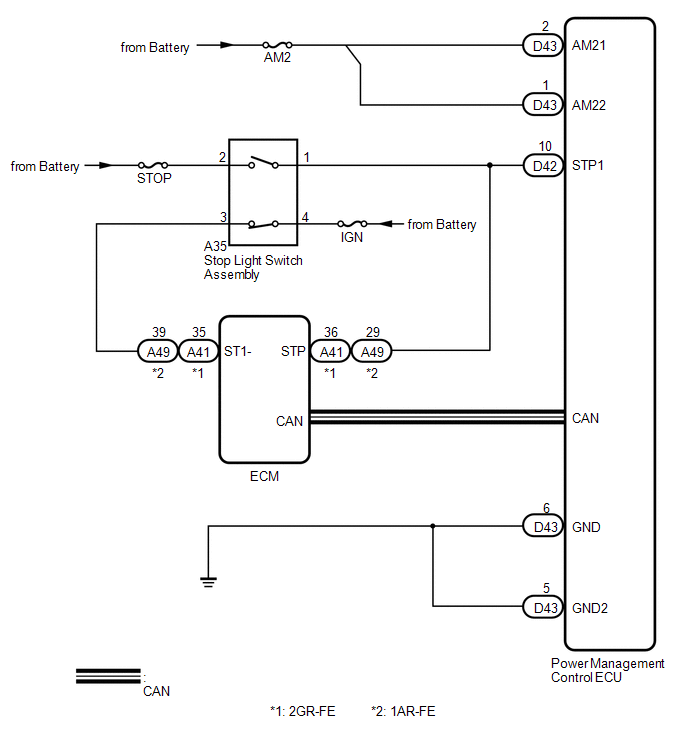
The power management control ECU receives brake signal information from 2 sources. It receives a signal from the stop light switch assembly via a direct line, and a signal from the ECM via CAN. If the information from these 2 sources is inconsistent, this DTC will be stored.
|
DTC No. |
DTC Detection Condition |
Trouble Area |
|---|---|---|
|
B2284 |
Stop light switch assembly operation information received by the power management control ECU from the stop light switch assembly via a direct line and stop light switch assembly information from the ECM via CAN are inconsistent. |
|
WIRING DIAGRAM
CAUTION / NOTICE / HINT
NOTICE:
- When the power management control ECU is replaced with a new one and the cable from the negative (-) battery terminal is connected, the power source mode becomes the on (IG) mode. When the battery is removed and reinstalled, the power source mode that was selected when the battery was removed is restored.
- Inspect the fuse for circuits related to this system before performing the following inspection procedure.
HINT:
Check the connector connection to the terminal to make sure that there is no abnormality such as a loose connection, deformation, etc.
PROCEDURE
|
1. |
CHECK HARNESS AND CONNECTOR (BATTERY - POWER MANAGEMENT CONTROL ECU) |
.gif)
| NG | .gif) |
REPAIR OR REPLACE HARNESS OR CONNECTOR (BATTERY - POWER MANAGEMENT CONTROL ECU) |
|
.gif)
|
2. |
CHECK HARNESS AND CONNECTOR (POWER MANAGEMENT CONTROL ECU - BODY GROUND) |
| NG | |
REPAIR OR REPLACE HARNESS OR CONNECTOR (POWER MANAGEMENT CONTROL ECU - BODY GROUND) |
|
|
3. |
INSPECT STOP LIGHT SWITCH ASSEMBLY |
|
(a) Remove the stop light switch assembly (See page
|
|
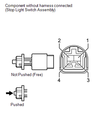
(b) Measure the resistance according to the value(s) in the table below.
Standard Resistance:
|
Tester Connection |
Condition |
Specified Condition |
|---|---|---|
|
1 - 2 |
Pushed |
10 kΩ or higher |
|
3 - 4 |
Pushed |
10 kΩ or higher |
|
1 - 2 |
Not pushed |
Below 1 Ω |
|
3 - 4 |
Not pushed |
Below 1 Ω |
| NG | |
REPLACE STOP LIGHT SWITCH ASSEMBLY |
|
|
4. |
CHECK HARNESS AND CONNECTOR (STOP LIGHT SWITCH ASSEMBLY - POWER MANAGEMENT CONTROL ECU) |
(a) Disconnect the D42 connector from the power management control ECU.
(b) Measure the resistance according to the value(s) in the table below.
Standard Resistance:
|
Tester Connection |
Condition |
Specified Condition |
|---|---|---|
|
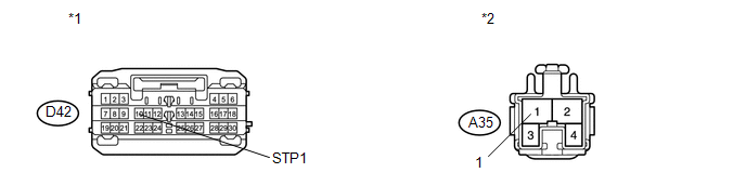
D42-10 (STP1) - A35-1 |
Always |
Below 1 Ω |
|
D42-10 (STP1) - Body ground |
Always |
10 kΩ or higher |
|
*1 |
Front view of wire harness connector (to Power Management Control ECU) |
*2 |
Front view of wire harness connector (to Stop Light Switch Assembly) |
| NG | |
REPAIR OR REPLACE HARNESS OR CONNECTOR (STOP LIGHT SWITCH ASSEMBLY - POWER MANAGEMENT CONTROL ECU) |
|
|
5. |
READ VALUE USING TECHSTREAM (STOP LIGHT SWITCH ASSEMBLY) |
(a) Connect the Techstream to the DLC3.
(b) Turn the engine switch on (IG).
(c) Turn the Techstream on.
(d) Enter the following menus: Body Electrical / Power Source Control / Data List.
(e) Read the Data List according to the display on the Techstream.
Power Source Control|
Tester Display |
Measurement Item/Range |
Normal Condition |
Specified Condition |
|---|---|---|---|
|
Stop Light Switch1 |
Stop light switch1/ON or OFF |
ON: Brake pedal depressed OFF: Brake pedal released |
- |
|
Result |
Proceed to |
|---|---|
|
ON and OFF do not appear on the screen. |
A |
|
ON and OFF appear on the screen (for 2GR-FE). |
B |
|
ON and OFF appear on the screen (for 1AR-FE). |
C |
| A | |
REPLACE POWER MANAGEMENT CONTROL ECU |
| B | |
GO TO SFI SYSTEM (for 2GR-FE) |
| C | |
GO TO SFI SYSTEM (for 1AR-FE) |
 Ignition Hold Monitor Malfunction (B2271)
DESCRIPTION
This DTC is stored when a problem such as an open in the AM2 fuse, an open or
short in the wire harness between the fuse and power management control ECU, a short
in the IG output cir ...
 ACC Monitor Malfunction (B2274)
DESCRIPTION
This DTC is stored when there is a problem in the ACC output circuit. The ACC
circuit is the circuit that goes from inside the power management control ECU to
the ACC relay.
...
Other materials about Toyota Venza:
Abbreviations Used In Manual
ABBREVIATIONS USED IN MANUAL
Abbreviation
Meaning
ABS
Anti-Lock Brake System
A/C
Air Conditioner
AC
Alternating Current
ACC
A ...
Inspection
INSPECTION
PROCEDURE
1. INSPECT FRONT SEAT FRAME WITH ADJUSTER LH
(a) Check operation of the seat frame (slide motor).
(1) w/ Memory:
Check if the seat frame moves smoothly when the battery is connected
to the slide motor connector termin ...
Problem Symptoms Table
PROBLEM SYMPTOMS TABLE
HINT:
Use the table below to help determine the cause of problem symptoms.
If multiple suspected areas are listed, the potential causes of the symptoms
are listed in order of probability in the "Suspected Area" ...

0.1605