Toyota Venza: Components
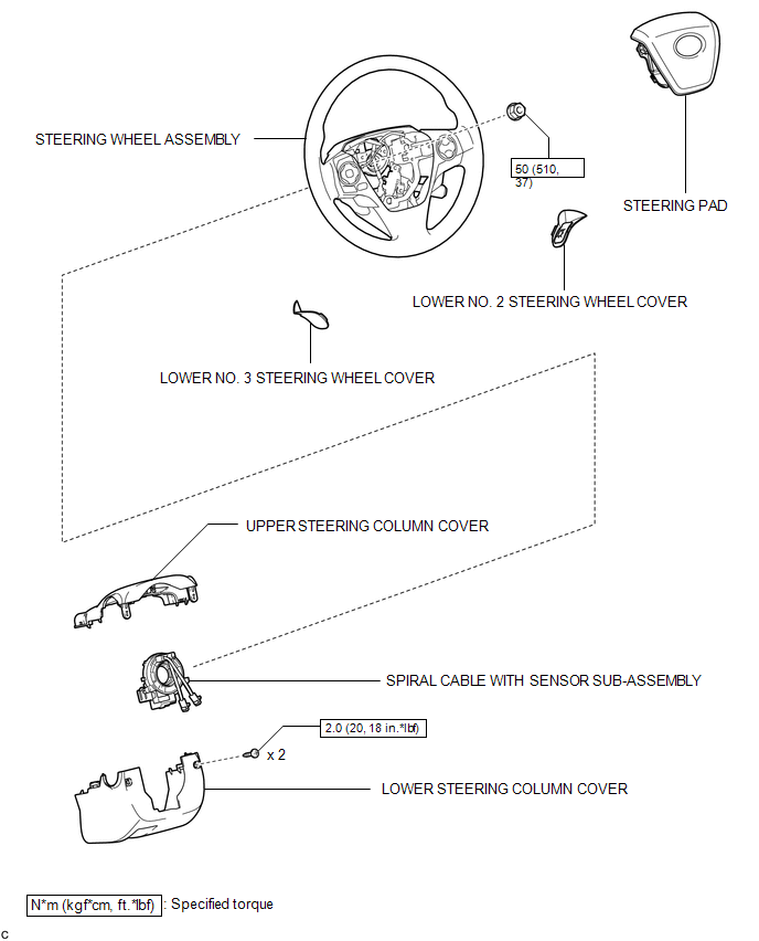
COMPONENTS
ILLUSTRATION
 Spiral Cable
...
 Inspection
INSPECTION
PROCEDURE
1. INSPECT SPIRAL CABLE
(a) Visually check for defects with the spiral cable removed from the vehicle.
(1) The defects are as follows:
Scratches on the spiral cable
...
Other materials about Toyota Venza:
Disassembly
DISASSEMBLY
CAUTION / NOTICE / HINT
HINT:
Use an overhaul stand as necessary.
PROCEDURE
1. REMOVE REAR DIFFERENTIAL FILLER PLUG
(a) Remove the rear differential filler plug and gasket.
2. INSPECT ...
Precaution
PRECAUTION
NOTICE:
When disconnecting the cable from the negative (-) battery terminal, initialize
the following systems after the cable is reconnected.
System Name
See Procedure
Back Door Closer System
...
Inspection
INSPECTION
PROCEDURE
1. INSPECT SPIRAL CABLE
(a) Visually check for defects with the spiral cable removed from the vehicle.
(1) The defects are as follows:
Scratches on the spiral cable
Small cracks the spiral cable
Dents on the spiral cabl ...

0.1547