Toyota Venza: Inspection
INSPECTION
PROCEDURE
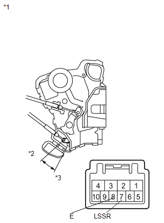
1. INSPECT FRONT DOOR LOCK ASSEMBLY LH
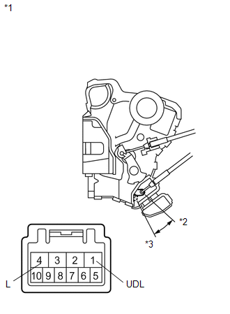
(a) Check the operation of the door lock motor.
|
(1) Apply battery voltage and check the operation of the door lock motor. OK:
If the result is not as specified, replace the front door lock assembly LH. |
|
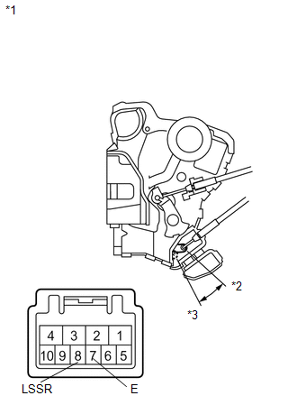
(b) Check the operation of the door unlock detection switch.
|
(1) Measure the resistance according to the value(s) in the table below. Standard Resistance:
If the result is not as specified, replace the front door lock assembly LH. |
|
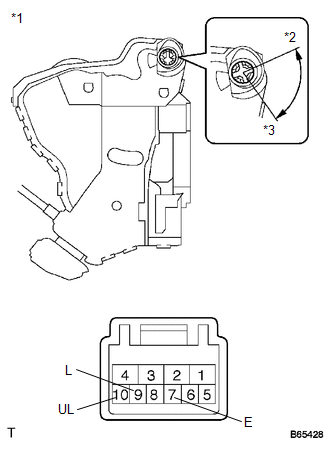
(c) Check the operation of the door key lock and unlock switch.
|
(1) Measure the resistance according to the value(s) in the table below. Standard Resistance:
If the result is not as specified, replace the front door lock assembly LH. |
|
2. INSPECT FRONT DOOR LOCK ASSEMBLY RH
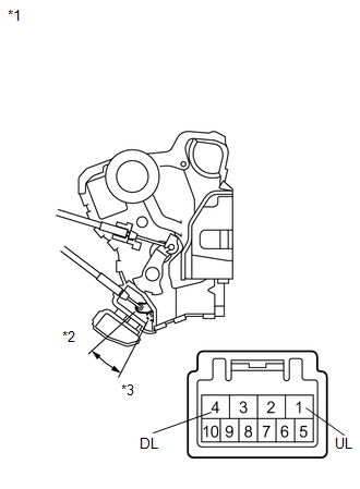
(a) Check the operation of the door lock motor.
|
(1) Apply battery voltage and check the operation of the door lock motor. OK:
If the result is not as specified, replace the front door lock assembly RH. |
|
(b) Check the operation of the door unlock detection switch.
|
(1) Measure the resistance according to the value(s) in the table below. Standard Resistance:
If the result is not as specified, replace the front door lock assembly RH. |
|
 Removal
REMOVAL
PROCEDURE
1. DISCONNECT CABLE FROM NEGATIVE BATTERY TERMINAL
CAUTION:
Wait at least 90 seconds after disconnecting the cable from the negative (-)
battery terminal to disable the SRS sys ...
 Installation
INSTALLATION
PROCEDURE
1. INSTALL FRONT DOOR LOCK ASSEMBLY
NOTICE:
When reusing the removed front door lock assembly, replace the door
lock wiring harness seal on the connector with a ...
Other materials about Toyota Venza:
Installation
INSTALLATION
PROCEDURE
1. INSPECT TORQUE CONVERTER ASSEMBLY
2. INSTALL TORQUE CONVERTER ASSEMBLY
(a) Engage the splines of the input shaft and turbine runner.
(b) Engage the splines o ...
Components
COMPONENTS
ILLUSTRATION
ILLUSTRATION
ILLUSTRATION
ILLUSTRATION
ILLUSTRATION
ILLUSTRATION
ILLUSTRATION
...
How To Proceed With Troubleshooting
CAUTION / NOTICE / HINT
HINT:
Use the following procedure to troubleshoot the intuitive parking assist
system.
*: Use the Techstream.
PROCEDURE
1.
VEHICLE BROUGHT TO WORKSHOP
NEXT ...

0.1438