Toyota Venza: Removal
REMOVAL
PROCEDURE
1. REMOVE BACK DOOR PANEL TRIM ASSEMBLY
.gif)
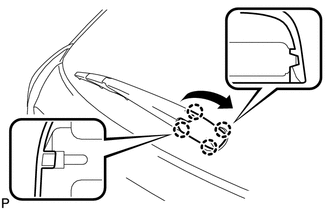
2. REMOVE REAR WIPER ARM HEAD CAP
|
(a) Disengage the 4 claws and remove the rear wiper arm head cap as shown in the illustration. |
|
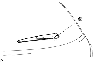
3. REMOVE REAR WIPER ARM AND BLADE ASSEMBLY
|
(a) Remove the nut and the rear wiper arm and blade assembly. |
|
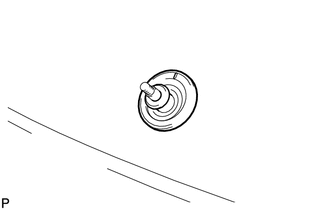
4. REMOVE REAR WIPER MOTOR GROMMET
|
(a) Remove the rear wiper motor grommet. |
|
5. REMOVE REAR WIPER MOTOR AND BRACKET ASSEMBLY
|
(a) Disconnect the connector. |
|
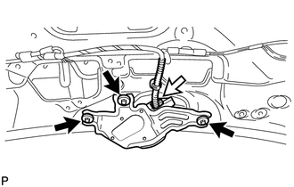
(b) Remove the 3 bolts and the rear wiper motor and bracket assembly.
 On-vehicle Inspection
ON-VEHICLE INSPECTION
PROCEDURE
1. INSPECT REAR WIPER MOTOR AND BRACKET ASSEMBLY
(a) Operate the rear wiper motor and bracket assembly.
(b ...
 Inspection
INSPECTION
PROCEDURE
1. INSPECT REAR WIPER MOTOR AND BRACKET ASSEMBLY
(a) Check the wiper low operation.
(1) Connect a battery positive (+) lead to terminal 4 (+B), and a negative (-)
lead to ...
Other materials about Toyota Venza:
Engine Hood Courtesy Switch Circuit
DESCRIPTION
The security courtesy switch is installed together with the hood lock. This switch
turns off when the engine hood is opened and turns on when the engine hood is closed.
WIRING DIAGRAM
PROCEDURE
1.
INSPECT HOOD LOCK AS ...
Intake Air Temperature Sensor Gradient Too High (P0111)
DESCRIPTION
The intake air temperature sensor, mounted on the mass air flow meter,
monitors the intake air temperature. The intake air temperature sensor has
a built-in thermistor with a resistance that varies according to the temperature
...
Evaporative Emission System Switching Valve Control Circuit High (P2420)
DTC SUMMARY
DTC No.
Monitoring Item
Malfunction Detection Condition
Trouble Area
Detection Timing
Detection Logic
P2420
Vent valve stuck open (vent)
Follo ...

0.141