Toyota Venza: Inspection
INSPECTION
CAUTION / NOTICE / HINT
NOTICE:
Ensure that fingers or articles of clothing do not get caught in moving parts when performing this test.
PROCEDURE
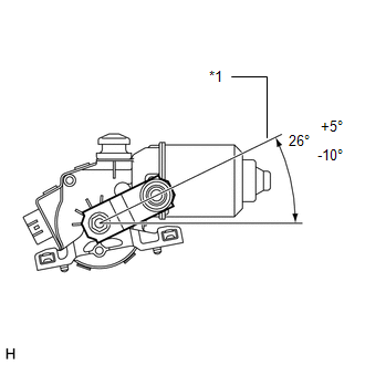
1. INSPECT WINDSHIELD WIPER MOTOR ASSEMBLY
|
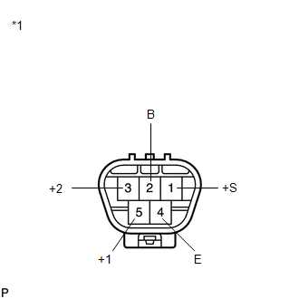
(a) Check the LO operation. (1) Connect a battery positive (+) lead to terminal 5 (+1) and a negative (-) lead to terminal 4 (E), and check that the motor operates at low speed (LO). OK: Motor operates at low speed (LO). Text in Illustration
|
|
(b) Check the HI operation.
(1) Connect a battery positive (+) lead to terminal 3 (+2) and a negative (-) lead to terminal 4 (E), and check that the motor operates at high speed (HI).
OK:
Motor operates at high speed (HI).
(c) Check the automatic stop (park) operation.
(1) Connect a battery positive (+) lead to terminal 5 (+1) and a negative (-) lead to terminal 4 (E). With the motor operating at low speed (LO), disconnect terminal 5 (+1) to stop the wiper motor operation at any position other than the matchmark.
(2) Using SST, connect terminals 1 (+S) and 5 (+1). Then connect a battery positive (+) lead to terminal 2 (B) and a negative (-) lead to terminal 4 (E) to restart the motor operation at low speed (LO).
SST: 09843-18040
|
(3) Check that the motor stops automatically at the automatic stop (park) position. OK: Motor stops automatically at the position. If the result is not as specified, replace the windshield wiper motor assembly. Text in Illustration
|
|
 On-vehicle Inspection
ON-VEHICLE INSPECTION
PROCEDURE
1. INSPECT WINDSHIELD WIPER MOTOR ASSEMBLY
(a) for RH Side
(1) Operate the windshield wiper motor assembly.
...
 Removal
REMOVAL
PROCEDURE
1. REMOVE FRONT WIPER ARM HEAD CAP
(a) Using a screwdriver, remove the 2 front wiper arm head caps as shown
in the illustration.
Text in Illustration
...
Other materials about Toyota Venza:
Console Box Light
Components
COMPONENTS
ILLUSTRATION
Removal
REMOVAL
PROCEDURE
1. REMOVE UPPER CONSOLE PANEL SUB-ASSEMBLY (w/o Seat Heater System)
2. REMOVE UPPER CONSOLE PANEL SUB-ASSEMBLY (w/ Seat Heater System)
3. REMOVE NO. 2 CONSOLE BOX CARPET
4. RE ...
Monitor Drive Pattern
MONITOR DRIVE PATTERN
1. TEST MONITOR DRIVE PATTERN FOR ECT
CAUTION:
Perform this drive pattern on a level surface and strictly observe the posted
speed limits and traffic laws while driving.
HINT:
Performing this drive pattern is one method to simulate ...
Installation
INSTALLATION
PROCEDURE
1. INSTALL DRIVE MONITOR SWITCH
(a) Engage the 4 claws to install the driver monitor switch.
2. INSTALL RADIO AND DISPLAY RECEIVER ASSEMBLY WITH BRACKET (for Radio and Display ...

0.1719