Toyota Venza: Removal
REMOVAL
PROCEDURE
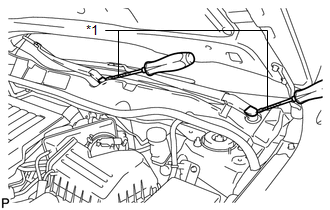
1. REMOVE FRONT WIPER ARM HEAD CAP
|
(a) Using a screwdriver, remove the 2 front wiper arm head caps as shown in the illustration. Text in Illustration
HINT: Tape the screwdriver tip before use. |
|
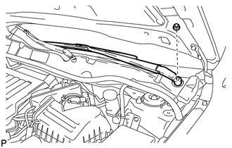
2. REMOVE FRONT WIPER ARM AND BLADE ASSEMBLY LH
|
(a) Remove the nut and the front wiper arm and blade assembly LH. |
|
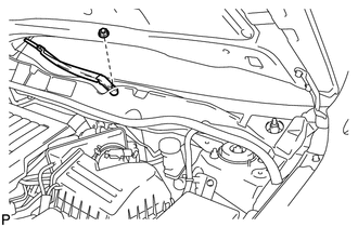
3. REMOVE FRONT WIPER ARM AND BLADE ASSEMBLY RH
|
(a) Remove the nut and the front wiper arm and blade assembly RH. |
|
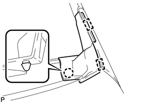
4. REMOVE FRONT FENDER TO COWL SIDE SEAL LH
|
(a) Disengage the claw and 2 guides and remove the front fender to cowl side seal LH. |
|
5. REMOVE FRONT FENDER TO COWL SIDE SEAL RH
HINT:
Use the same procedure for the RH side and LH side.
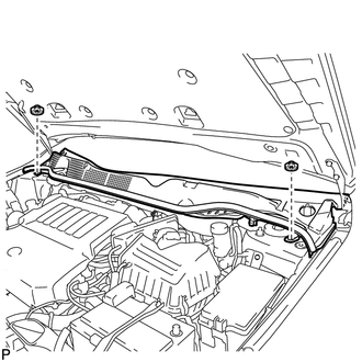
6. REMOVE COWL TOP VENTILATOR LOUVER SUB-ASSEMBLY
|
(a) Using a clip remover, remove the 2 clips. |
|
|
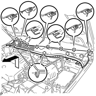
(b) Disengage the 13 claws and pull out the cowl top ventilator louver sub-assembly as shown in the illustration. |
|
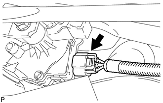
7. REMOVE WINDSHIELD WIPER MOTOR AND LINK ASSEMBLY
|
(a) Disconnect the connector. |
|
|
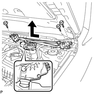
(b) Remove the 3 bolts and the windshield wiper motor and link assembly as shown in the illustration. |
|
8. REMOVE WINDSHIELD WIPER MOTOR ASSEMBLY
|
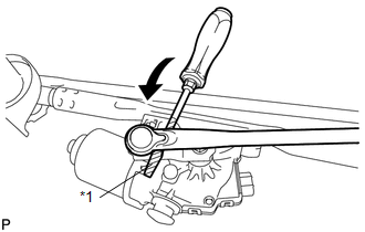
(a) Using a screwdriver, disengage the windshield wiper link rod from the crank arm pivot of the front wiper motor assembly as shown in the illustration. Text in Illustration
HINT: Tape the screwdriver tip before use. |
|
|
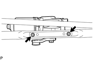
(b) Using a T30 "TORX" socket wrench, remove the 2 bolts and the windshield wiper motor assembly from the windshield wiper link assembly. |
|
 Inspection
INSPECTION
CAUTION / NOTICE / HINT
NOTICE:
Ensure that fingers or articles of clothing do not get caught in moving parts
when performing this test.
PROCEDURE
1. INSPECT WINDSHIELD WIPER MOTOR A ...
 Installation
INSTALLATION
PROCEDURE
1. INSTALL WINDSHIELD WIPER MOTOR ASSEMBLY
(a) Using a T30 "TORX" socket wrench, install the windshield wiper motor
assembly with the 2 bolts.
Tor ...
Other materials about Toyota Venza:
Removal
REMOVAL
PROCEDURE
1. REMOVE REAR WHEELS
2. REMOVE CENTER EXHAUST PIPE ASSEMBLY
(a) Remove the center exhaust pipe assembly.
HINT:
Refer to the instructions for Removal of the exhaust pipe (See page
for 2GR-FE,
for 1AR-FE).
3. REMOVE LOWER NO. 1 EXH ...
Engine Control System Malfunction (C1201/51)
DESCRIPTION
If a malfunction in the engine control system is detected, the operations of
VSC and TRAC are prohibited by the fail-safe function. When the signals from the
engine are input normally, the fail-safe is cancelled and the DTC is not stored.
...
Fuel Injector Circuit
DESCRIPTION
The fuel injector assemblies are located on the intake manifold. They inject
fuel into the cylinders based on signals from the ECM.
WIRING DIAGRAM
CAUTION / NOTICE / HINT
NOTICE:
Inspect the fuses for circuits related to this system befo ...

0.1566