Toyota Venza: System Diagram
SYSTEM DIAGRAM
 Communication Method
|
Transmitting ECU |
Receiver |
Signal |
Communication Method |
|---|---|---|---|
|
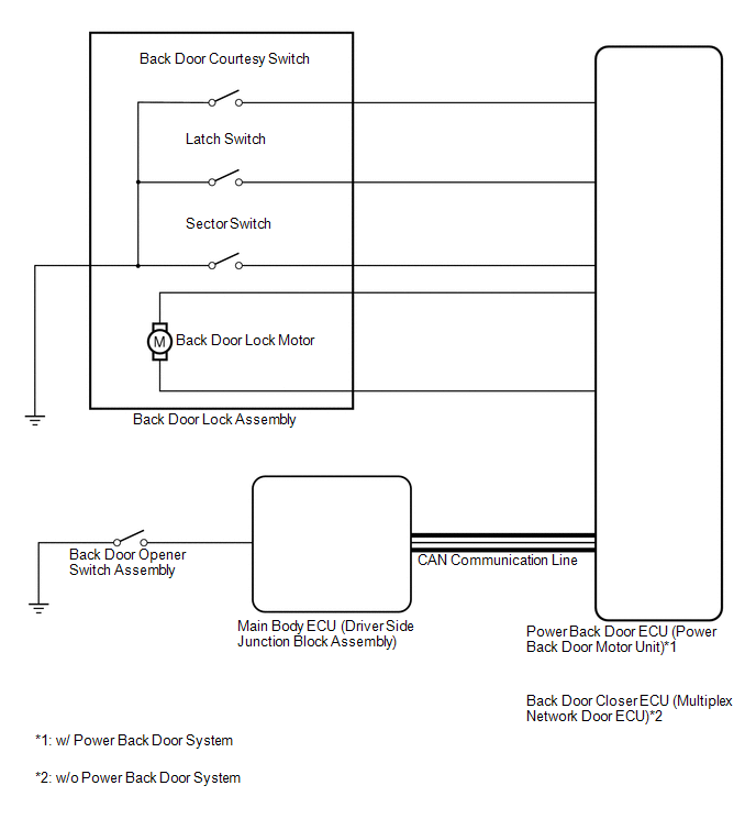
Main body ECU (Driver Side Junction Block Assembly) |
Power back door ECU (Power back door motor unit)*1 Back door closer ECU (Multiplex network door ECU)*2 |
Back door opener switch signal |
CAN |
- *1: w/ Power Back Door System
- *2: w/o Power Back Door System
 Parts Location
PARTS LOCATION
ILLUSTRATION
...
 System Description
SYSTEM DESCRIPTION
1. BACK DOOR CLOSER SYSTEM DESCRIPTION
(a) Operating any power back door switch when the back door is fully closed inputs
a request signal to the power back door ECU*1 or back d ...
Other materials about Toyota Venza:
Engine Hood Courtesy Switch Circuit
DESCRIPTION
The security courtesy switch is installed together with the hood lock. This switch
turns off when the engine hood is opened and turns on when the engine hood is closed.
WIRING DIAGRAM
PROCEDURE
1.
INSPECT HOOD LOCK AS ...
Brake Switch "B" Circuit High (P0724)
DESCRIPTION
The purpose of this circuit is to prevent the engine from stalling when the brakes
are suddenly applied while driving in the lock-up condition.
When the brake pedal is depressed, this switch sends a signal to the TCM. Then
the TCM cancels the ...
Tire inflation pressure
- Tire inflation pressure
The recommended cold tire inflation pressure and tire size is displayed on the
tire and loading information label.
- Inspection and adjustment procedure
1. Tire valve
2. Tire pressure gauge
Remove the tire val ...

0.1385