Toyota Venza: Components
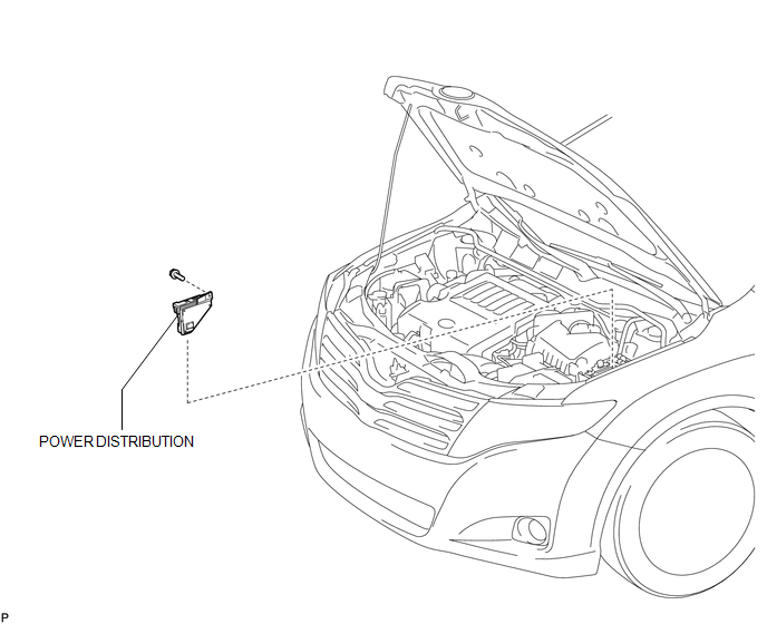
COMPONENTS
ILLUSTRATION

 Inspection
INSPECTION
PROCEDURE
1. INSPECT INTEGRATION RELAY
(a) Inner circuit (for 2GR-FE)
(1) for EFI MAIN relay
Measure the resistance according to the value(s) in the table
...
Other materials about Toyota Venza:
Inspection
INSPECTION
PROCEDURE
1. INSPECT REAR POWER WINDOW REGULATOR MOTOR ASSEMBLY LH
(a) Apply positive (+) battery voltage to connector terminal 2 (B).
NOTICE:
Do not apply positive (+) battery voltage to any terminals other than
terminal 2 ( ...
Stop Light Switch
Components
COMPONENTS
ILLUSTRATION
Removal
REMOVAL
PROCEDURE
1. REMOVE STOP LIGHT SWITCH ASSEMBLY
(a) Disconnect the connector.
(b) Turn the stop light switch assembly countercl ...
Installation
INSTALLATION
PROCEDURE
1. INSTALL VACUUM SWITCHING VALVE ASSEMBLY (for ACIS)
(a) Install the vacuum switching valve assembly (for ACIS) with the bolt.
Torque:
9.0 N·m {92 kgf·cm, 80 in·lbf}
...

0.1536