Toyota Venza: Inspection
INSPECTION
PROCEDURE
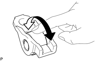
1. INSPECT NO. 1 VALVE ROCKER ARM SUB-ASSEMBLY
|
(a) Turn the roller by hand to check that it turns smoothly. If the roller does not turn smoothly, replace the No. 1 valve rocker arm sub-assembly. |
|
2. INSPECT VALVE LASH ADJUSTER ASSEMBLY
NOTICE:
- Keep the adjuster free from dirt and foreign matter.
- Use only clean engine oil.
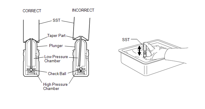
(a) Place the valve lash adjuster assembly into a container full of new engine oil.
(b) Insert the tip of SST into the lash adjuster plunger and use the tip to press down on the check ball inside the plunger.
SST: 09276-75010
(c) Squeeze SST and the lash adjuster together to move the plunger up and down 5 to 6 times.
(d) Check the movement of the plunger and bleed air.
OK:
Plunger moves up and down.
NOTICE:
When bleeding air from the high-pressure chamber, make sure that the tip of SST is actually pressing the check ball as shown in the illustration. If the check ball is not pressed, air will not bleed.
(e) After bleeding the air, remove SST. Then try to quickly and firmly press the plunger with your fingers.
OK:
Plunger is very difficult to move.
If the result is not as specified, replace the valve lash adjuster assembly.
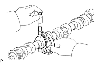
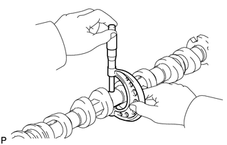
3. INSPECT CAMSHAFT OIL CLEARANCE
.gif)
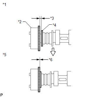
4. INSPECT CAMSHAFT THRUST CLEARANCE
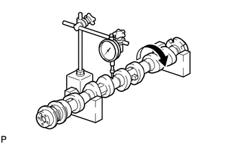
5. INSPECT CAMSHAFT
|
(a) Inspect the camshaft runout. (1) Place the camshaft on V-blocks. (2) Using a dial indicator, measure the circle runout at the center journal. Maximum circle runout: 0.03 mm (0.00118 in.) If the circle runout is more than the maximum, replace the camshaft. HINT: Check the oil clearance after replacing the camshaft. |
|
|
(b) Inspect the cam lobes. (1) Using a micrometer, measure the cam lobe height. Standard Cam Lobe Height:
Minimum Cam Lobe Height:
If the cam lobe height is less than the minimum, replace the camshaft. |
|
|
(c) Inspect the camshaft journals. (1) Using a micrometer, measure the journal diameter. Standard Journal Diameter:
If the journal diameter is not as specified, check the oil clearance
(See page |
|
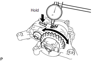
6. INSPECT CAMSHAFT TIMING GEAR ASSEMBLY
|
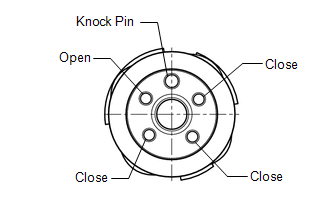
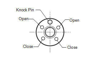
(a) Align and attach the knock pin of the camshaft with the pin hole of the camshaft timing gear assembly. Text in Illustration
|
|
.png)
|
(b) Check that there is no clearance between the camshaft timing gear assembly and camshaft flange. Text in Illustration
|
|
(c) Secure the camshaft in place by hand, and then install the installation bolt of the camshaft timing gear assembly by hand.
NOTICE:
Do not use any tools to install the bolt. If the bolt is installed using a tool, the lock pin will be damaged.
(d) Check the lock of the camshaft timing gear assembly.
(1) Make sure that the camshaft timing gear assembly is locked.
NOTICE:
Be careful not to damage the camshaft.
(e) Release the lock pin.
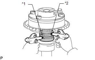
(1) Clean the camshaft journal with non-residue solvent.
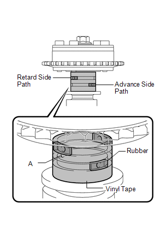
(2) Cover the 4 oil paths of the cam journal with vinyl tape as shown in the illustration.
HINT:
There are 4 oil paths in the grooves of the camshaft. Plug three of the paths with pieces of rubber.
(3) Open a hole at port A shown in the illustration.
|
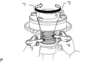
(4) While applying approximately 200 kPa (2.0 kgf/ cm2, 29 psi) of air pressure to the oil path, forcibly turn the camshaft timing gear assembly in the advance direction (counterclockwise). CAUTION: Cover the paths with a piece of cloth when applying pressure to keep oil from spraying. NOTICE: Do not allow the camshaft timing gear assembly to lock. If it locks, release the lock pin again. HINT:
|
|
.png)
(f) Check for smooth rotation.
(1) Turn the camshaft timing gear assembly within its movable range (19 to 21°) 2 or 3 times, but do not turn it to the most retarded position. Make sure that the camshaft timing gear assembly turns smoothly.
NOTICE:
Do not allow the camshaft timing gear assembly to lock.
If it locks, release the lock pin again.
(g) Remove the vinyl tape and rubber pieces from the camshaft.
(h) Remove the bolt and camshaft timing gear assembly.
7. INSPECT CAMSHAFT TIMING EXHAUST GEAR ASSEMBLY
|
(a) Align and attach the knock pin of the No. 2 camshaft with the pin hole of the camshaft timing exhaust gear assembly. Text in Illustration
|
|
.png)
|
(b) Check that there is no clearance between the camshaft timing exhaust gear assembly and No. 2 camshaft flange. Text in Illustration
|
|
(c) Secure the No. 2 camshaft in place by hand, and then install the installation bolt of the camshaft timing exhaust gear assembly by hand.
(d) Check the lock of the camshaft timing exhaust gear assembly.
(1) Make sure that the camshaft timing exhaust gear assembly is locked.
NOTICE:
Be careful not to damage the No. 2 camshaft.
(e) Release the lock pin.
(1) Clean the No. 2 camshaft journal with non-residue solvent.
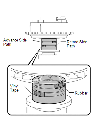
(2) Cover the 4 oil paths of the cam journal with vinyl tape as shown in the illustration.
HINT:
There are 4 oil paths in the grooves of the No. 2 camshaft. Plug 2 paths with rubber pieces.
(3) Prick a hole in the tape placed on the advance side path. Prick a hole in the tape placed on the retard side path, on the opposite side to that of the advance side path, as shown in the illustration.
|
(4) Apply approximately 200 kPa (2.0 kgf/cm2, 29 psi) of air pressure to the 2 open paths (the advance side path and retard side path). Text in Illustration
NOTICE: Cover the paths with a piece of cloth when applying pressure to keep oil from spraying. |
|
|
(5) Check that the camshaft timing exhaust gear assembly turns in the retard direction when reducing the air pressure applied to the advance side path. Text in Illustration
HINT: The lock pin is released and the camshaft timing exhaust gear assembly turns in the retard direction. |
|
(6) When the camshaft timing exhaust gear assembly moves to the most retarded position, release the air pressure from the advance side path, and then release the air pressure from the retard side path.
NOTICE:
Be sure to release the air pressure from the advance side path first. If the air pressure of the retard side path is released first, the camshaft timing exhaust gear assembly may abruptly shift in the advance direction and break the lock pin or other parts.
(f) Check for smooth rotation.
(1) Turn the camshaft timing exhaust gear assembly within its movable range (19 to 21°) 2 or 3 times, but do not turn it to the most advanced position. Make sure that the camshaft timing exhaust gear assembly turns smoothly.
NOTICE:
When the air pressure is released from the advance side path and then from the retard side path, the gear automatically returns to the most advanced position due to the advance assist spring operation, and locks. Gradually release the air pressure from the retard side path before performing the smooth rotation check.
(g) Check the lock at the most advanced position.
(1) Make sure that the camshaft timing exhaust gear assembly locks at the most advanced position.
(h) Remove the vinyl tape and rubber pieces from the No. 2 camshaft.
(i) Remove the bolt and camshaft timing gear assembly.
8. INSPECT CHAIN SUB-ASSEMBLY
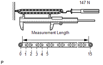
(a) Using a spring scale, pull the chain sub-assembly with a force of 147 N (15 kgf, 33.0 lbf) as shown in the illustration.
(b) Using a vernier caliper, measure the length of 15 links.
Maximum chain elongation:
137.7 mm (5.42 in.)
HINT:
Perform the measurement at 3 random places.
If the elongation is more than the maximum, replace the chain sub-assembly.
9. INSPECT CRANKSHAFT TIMING SPROCKET
|
(a) Place the chain sub-assembly around the crankshaft timing sprocket. |
|
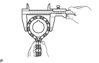
(b) Using a vernier caliper, measure the crankshaft timing sprocket diameter with the chain sub-assembly.
Minimum sprocket diameter (with chain):
59.94 mm (2.36 in.)
If the diameter is less than the minimum, replace the chain sub-assembly and crankshaft timing sprocket.
HINT:
The vernier caliper must contact the chain rollers for the measurement.
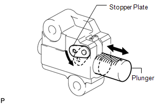
10. INSPECT NO. 1 CHAIN TENSIONER ASSEMBLY
|
(a) Move the stopper plate counterclockwise to release the lock. Push the plunger and check that it moves smoothly. If necessary, replace the No. 1 chain tensioner assembly. |
|
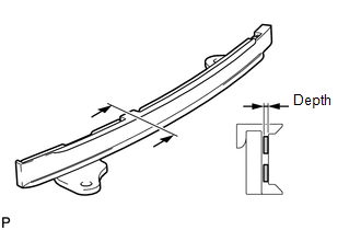
11. INSPECT CHAIN TENSIONER SLIPPER
|
(a) Measure the worn depth of the chain tensioner slipper. Maximum depth: 1.0 mm (0.0394 in.) If the depth is more than the maximum, replace the chain tensioner slipper. |
|
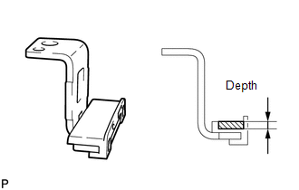
12. INSPECT NO. 1 CHAIN VIBRATION DAMPER
|
(a) Measure the worn depth of the No. 1 chain vibration damper. Maximum depth: 1.0 mm (0.0394 in.) If the depth is more than the maximum, replace the No. 1 chain vibration damper. |
|
13. INSPECT TIMING CHAIN GUIDE
|
(a) Measure the worn depth of the timing chain guide. Maximum depth: 1.0 mm (0.0394 in.) If the depth is more than the maximum, replace the timing chain guide. |
|
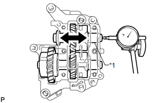
14. INSPECT BALANCE SHAFT THRUST CLEARANCE
|
(a) Using a dial indicator, measure the thrust clearance while moving the No. 1 balance shaft back and forth. Text in Illustration
Standard thrust clearance: 0.05 to 0.09 mm (0.00197 to 0.00354 in.) Maximum thrust clearance: 0.09 mm (0.00354 in.) If the thrust clearance is more than the maximum, replace the engine balancer assembly. |
|
|
(b) Using a dial indicator, measure the thrust clearance while moving the No. 2 balance shaft back and forth. Text in Illustration
Standard thrust clearance: 0.05 to 0.09 mm (0.00197 to 0.00354 in.) Maximum thrust clearance: 0.09 mm (0.00354 in.) If the thrust clearance is more than the maximum, replace the engine balancer assembly. |
|
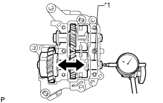
15. INSPECT BALANCE SHAFT BACKLASH
|
(a) Secure the No. 2 balance shaft in place, and then using a dial indicator, measure the backlash of the No. 1 and No. 2 balance shafts as shown in the illustration. Standard backlash: 0.04 to 0.16 mm (0.00157 to 0.00630 in.) Maximum backlash: 0.16 mm (0.00630 in.) NOTICE: Measure at 3 or more areas around the circumference of the No. 1 and No. 2 balance shafts. If the backlash is more than the maximum, replace the engine balancer assembly. |
|
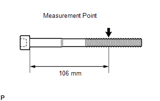
16. INSPECT CYLINDER HEAD BOLT
|
(a) Using a vernier caliper, measure the diameter of the threads at the measurement point. Standard diameter: 10.85 to 11.00 mm (0.427 to 0.433 in.) Minimum diameter: 10.6 mm (0.417 in.) Measurement point (distance from the seat): 106 mm (4.17 in.) HINT:
|
|
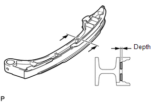
17. INSPECT EXHAUST MANIFOLD CONVERTER SUB-ASSEMBLY
|
(a) Using a precision straightedge and feeler gauge, measure the warpage of the surface that contacts the cylinder head. Maximum warpage: 0.7 mm (0.0276 in.) If the warpage is more than the maximum, replace the exhaust manifold converter sub-assembly. |
|
 Disassembly
DISASSEMBLY
PROCEDURE
1. REMOVE ENGINE COVER JOINT
(a) Remove the 3 joints.
2. REMOVE SPARK PLUG
3. REMOVE CAMSHAFT TIMING OIL CONTROL ...
 Installation
INSTALLATION
CAUTION / NOTICE / HINT
HINT:
Perform "Inspection After Repair" after replacing the engine assembly (See page
).
PROCEDURE
1. INSTALL IGNITION COIL ASSEMBLY
2. INSTAL ...
Other materials about Toyota Venza:
Lost Communication with ECM / PCM "A" (U0100,U0129)
DESCRIPTION
The combination meter assembly communicates with the ECM via the CAN communication
system (CAN No. 1 Bus).
DTC No.
DTC Detection Condition
Trouble Area
U0100
When either of the follow ...
How To Proceed With Troubleshooting
CAUTION / NOTICE / HINT
HINT:
Use the following procedure to troubleshoot the window defogger system.
*: Use the Techstream.
PROCEDURE
1.
VEHICLE BROUGHT TO WORKSHOP
NEXT
...
Sliding Roof Switch Assembly
Components
COMPONENTS
ILLUSTRATION
Removal
REMOVAL
PROCEDURE
1. REMOVE MAP LIGHT ASSEMBLY
Inspection
INSPECTION
PROCEDURE
1. INSPECT SLIDING ROOF SWITCH (ROOF CONSOLE BOX ASSEMBLY)
(a) Measure the resistance according to the value(s) in ...

0.1752