Toyota Venza: Components
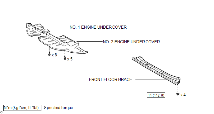
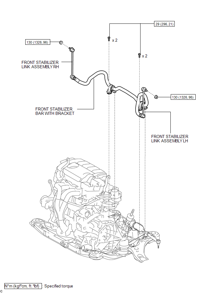
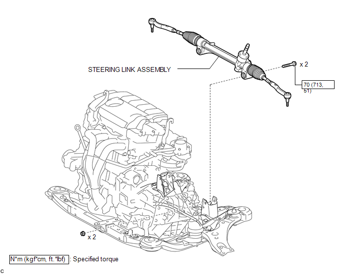
COMPONENTS
ILLUSTRATION
ILLUSTRATION
.png)
ILLUSTRATION
ILLUSTRATION
ILLUSTRATION
.png)
ILLUSTRATION
.png)

 Removal
REMOVAL
CAUTION / NOTICE / HINT
NOTICE:
When disconnecting the steering intermediate shaft assembly and pinion shaft
of the steering gear assembly, be sure to place matchmarks before servicing.
...
Other materials about Toyota Venza:
Removal
REMOVAL
PROCEDURE
1. REMOVE YAW RATE AND ACCELERATION SENSOR
HINT:
Refer to the instructions for Removal of the yaw rate and acceleration sensor
(See page ).
2. REMOVE REAR NO. 2 AIR DUCT
3. REMOVE REAR NO. 1 AIR DUCT
4. REMOVE FRONT NO. 2 FLOO ...
Cruise Main Indicator Light Circuit
DESCRIPTION
The ECM detects a cruise control main switch signal and sends it to
the combination meter assembly through CAN. Then the CRUISE main indicator
light comes on.
The CRUISE main indicator light circuit uses CAN for communication.
...
Removal
REMOVAL
CAUTION / NOTICE / HINT
CAUTION:
Wear protective gloves when removing the exhaust pipe.
The exhaust pipe is extremely hot immediately after the engine has stopped.
Confirm that the exhaust pipe has cooled down ...

0.1303