Toyota Venza: IG Power Source Circuit
DESCRIPTION
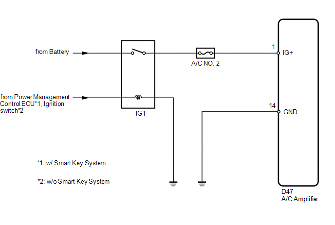
The main power source is supplied to the A/C amplifier when the ignition switch is ON.
The power source is used for operating the A/C amplifier and servo motor, etc.
WIRING DIAGRAM
CAUTION / NOTICE / HINT
NOTICE:
Inspect the fuses for circuits related to this system before performing the following inspection procedure.
HINT:
Start the engine before inspection. Check the IG1 relay or battery if the engine does not start.
PROCEDURE
|
1. |
INSPECT A/C AMPLIFIER |
|
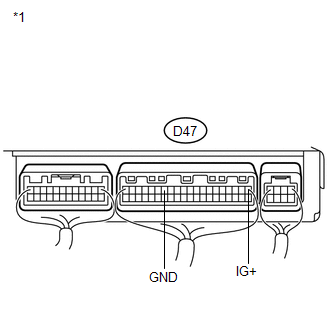
(a) Remove the A/C amplifier with its connectors still connected. |
|
(b) Measure the voltage according to the value(s) in the table below.
Standard Voltage:
|
Tester Connection |
Condition |
Specified Condition |
|---|---|---|
|
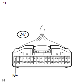
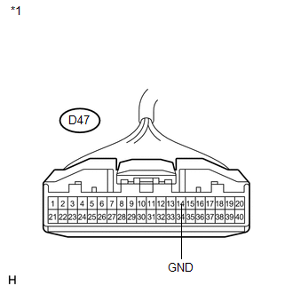
D47-1 (IG+) - D47-14 (GND) |
Ignition switch off |
Below 1 V |
|
D47-1 (IG+) - D47-14 (GND) |
Ignition switch ON |
11 to 14 V |
|
*1 |
Component with harness connected (A/C Amplifier) |
| OK | .gif) |
PROCEED TO NEXT SUSPECTED AREA SHOWN IN PROBLEM SYMPTOMS TABLE |
|
.gif)
|
2. |
CHECK HARNESS AND CONNECTOR (A/C AMPLIFIER - BATTERY) |
|
(a) Disconnect the A/C amplifier connector. |
|
(b) Measure the voltage according to the value(s) in the table below.
Standard Voltage:
|
Tester Connection |
Condition |
Specified Condition |
|---|---|---|
|
D47-1 (IG+) - Body ground |
Ignition switch off |
Below 1 V |
|
D47-1 (IG+) - Body ground |
Ignition switch ON |
11 to 14 V |
|
*1 |
Front view of wire harness connector (to A/C Amplifier) |
| NG | |
REPAIR OR REPLACE HARNESS OR CONNECTOR |
|
|
3. |
CHECK HARNESS AND CONNECTOR (A/C AMPLIFIER - BODY GROUND) |
|
(a) Measure the resistance according to the value(s) in the table below. Standard Resistance:
|
|
| OK | |
REPLACE A/C AMPLIFIER |
| NG | |
REPAIR OR REPLACE HARNESS OR CONNECTOR |
 Blower Motor Circuit
DESCRIPTION
The blower motor is operated by signals from the A/C amplifier. Blower motor
speed signals are transmitted in accordance with changes in the duty ratio.
WIRING DIAGRAM
CAUTION / NOT ...
 Back-up Power Source Circuit
DESCRIPTION
The back-up power source circuit for the A/C amplifier is shown below. Power
is supplied even when the ignition switch is turned off. The power is used for diagnostic
trouble code mem ...
Other materials about Toyota Venza:
Removal
REMOVAL
PROCEDURE
1. PRECAUTION (w/ Navigation System)
NOTICE:
After turning the ignition switch off, waiting time may be required before disconnecting
the cable from the negative (-) battery terminal. Therefore, make sure to read the
disconnecting the ...
Ignition Switch Circuit
DESCRIPTION
The main body ECU (driver side junction block assembly) determines the ignition
switch position (OFF, ACC, ON) based on signals from the IG or ACC circuit.
WIRING DIAGRAM
PROCEDURE
1.
READ VALUE USING TECHSTREAM
...
Seat Heater Switch
Components
COMPONENTS
ILLUSTRATION
Removal
REMOVAL
PROCEDURE
1. REMOVE UPPER CONSOLE PANEL SUB-ASSEMBLY
2. REMOVE SEAT HEATER SWITCH
(a) Disengage the 2 claws and remove the seat heater switch as shown
in the illustration.
...

0.1409