Toyota Venza: Blower Motor Circuit
DESCRIPTION
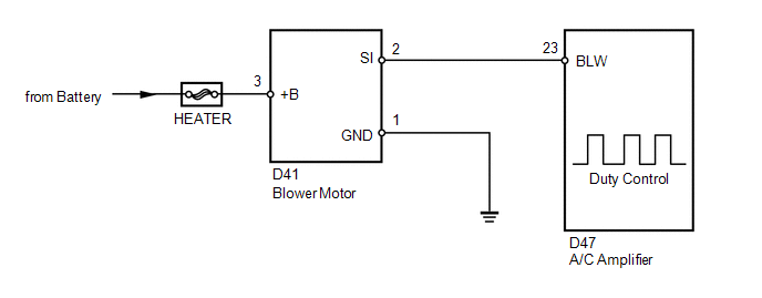
The blower motor is operated by signals from the A/C amplifier. Blower motor speed signals are transmitted in accordance with changes in the duty ratio.
WIRING DIAGRAM
CAUTION / NOTICE / HINT
NOTICE:
Inspect the fuses for circuits related to this system before performing the following inspection procedure.
PROCEDURE
|
1. |
PERFORM ACTIVE TEST USING TECHSTREAM |
(a) Connect the Techstream to the DLC3.
(b) Turn the ignition switch to ON.
(c) Turn the Techstream on.
(d) Enter the following menus: Body / Air Conditioner / Active Test.
(e) Check the operation by referring to the table below.
Air Conditioner|
Tester Display |
Test Part |
Control Range |
Diagnostic Note |
|---|---|---|---|
|
Blower Motor |
Blower motor |
Min.: 0, Max.: 31 |
- |
OK:
Blower motor operates and blower motor speed level changes.
|
Result |
Proceed to |
|---|---|
|
OK |
A |
|
NG (Blower motor does not operate) |
B |
|
NG (Blower motor operates but does not change speed) |
C |
| A | .gif) |
PROCEED TO NEXT SUSPECTED AREA SHOWN IN PROBLEM SYMPTOMS TABLE |
| C | |
GO TO STEP 6 |
|
.gif)
|
2. |
CHECK HARNESS AND CONNECTOR (BLOWER MOTOR - BODY GROUND) |
|
(a) Disconnect the blower motor connector. |
|
(b) Measure the resistance according to the value(s) in the table below.
Standard Resistance:
|
Tester Connection |
Condition |
Specified Condition |
|---|---|---|
|
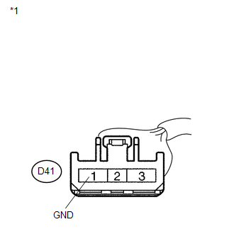
D41-1 (GND) - Body ground |
Always |
Below 1 Ω |
|
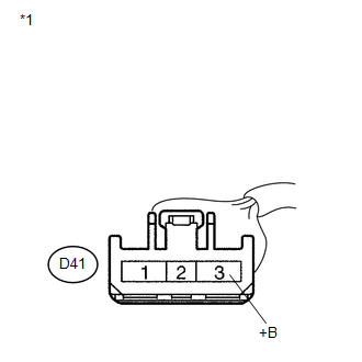
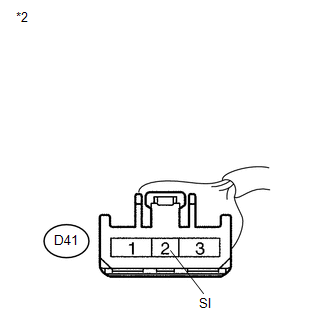
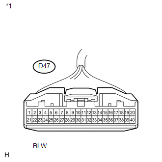
*1 |
Front view of wire harness connector (to Blower Motor) |
| NG | |
REPAIR OR REPLACE HARNESS OR CONNECTOR |
|
|
3. |
CHECK HARNESS AND CONNECTOR (BLOWER MOTOR - BATTERY) |
|
(a) Measure the voltage according to the value(s) in the table below. Standard Voltage:
|
|
| NG | |
REPAIR OR REPLACE HARNESS OR CONNECTOR |
|
|
4. |
CHECK HARNESS AND CONNECTOR (BLOWER MOTOR - A/C AMPLIFIER) |
|
(a) Disconnect the A/C amplifier connector. |
|

|
(b) Measure the resistance according to the value(s) in the table below. Standard Resistance:
|
|
| NG | |
REPAIR OR REPLACE HARNESS OR CONNECTOR |
|
|
5. |
INSPECT BLOWER MOTOR |
(a) Reconnect the blower motor connector.
|
(b) Measure the voltage according to the value(s) in the table below. Standard Voltage:
|
|
| NG | |
REPLACE BLOWER MOTOR |
|
|
6. |
INSPECT A/C AMPLIFIER |
|
(a) Remove the A/C amplifier. |
|
(b) Reconnect the A/C amplifier connector.
(c) Turn the ignition switch to ON.
(d) Turn the blower switch LO.
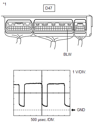
(e) Measure the waveform between terminal D47-23 (BLW) of the A/C amplifier and body ground.
|
Item |
Content |
|---|---|
|
Tool setting |
1 V/DIV., 500 μs/DIV. |
|
Vehicle condition |
Ignition switch ON Blower switch LO |
OK:
Waveform is as shown in the illustration.
HINT:
The waveform varies with the blower speed.
Text in Illustration|
*1 |
Component with harness connected (A/C Amplifier) |
| OK | |
REPLACE BLOWER MOTOR |
| NG | |
REPLACE A/C AMPLIFIER |
 Air Conditioning Compressor Magnetic Clutch Circuit
DESCRIPTION
When the A/C amplifier is turned on, a magnetic clutch ON signal is sent from
the MGC terminal of the A/C amplifier. Then, the MGC relay turns on to operate the
magnetic clutch.
WIRI ...
 IG Power Source Circuit
DESCRIPTION
The main power source is supplied to the A/C amplifier when the ignition switch
is ON.
The power source is used for operating the A/C amplifier and servo motor, etc.
WIRING DIAGRAM
...
Other materials about Toyota Venza:
Removal
REMOVAL
PROCEDURE
1. REMOVE FRONT SEAT HEADREST ASSEMBLY
2. REMOVE FRONT SEAT REAR OUTER TRACK COVER
3. REMOVE FRONT SEAT REAR INNER TRACK COVER
4. REMOVE FRONT SEAT ASSEMBLY
5. REMOVE SLIDE AND VERTICAL POWER SEAT SWITCH KNOB
6. REMOVE RECL ...
Components
COMPONENTS
ILLUSTRATION
ILLUSTRATION
ILLUSTRATION
ILLUSTRATION
ILLUSTRATION
...
Front Stabilizer Bar(for 2gr-fe 2wd)
Components
COMPONENTS
ILLUSTRATION
Removal
REMOVAL
PROCEDURE
1. REMOVE FRONT FRAME ASSEMBLY (When Using the Engine Support Bridge)
(See page )
2. REMOVE ENGINE ASSEMBLY WITH TRANSAXLE (When Not Using the Engine Support Bridge)
(See page )
3. ...

0.1259