Toyota Venza: High Temperature Adjustment
HIGH TEMPERATURE ADJUSTMENT
PROCEDURE
1. ADJUST FLUID LEVEL AT HIGH TEMPERATURE
CAUTION:
- Use caution while the engine is idling and the cooling fan is operating.
- Be careful not to burn yourself when the automatic transaxle fluid temperature is high.
(a) Warm up and stop the engine. [*4]
(b) Connect the Techstream to the DLC3 with the ignition switch off.
(c) Turn the ignition switch to ON and turn the Techstream on.
NOTICE:
To reduce load, make sure that all electrical systems, such as the air conditioning, lighting system, electric fan and audio system, are off.
(d) Enter the following menus: Powertrain / ECT / Data List.
(e) Select the Data List item: A/T Oil Temperature 1
(f) Select the Data List item: Engine Speed
(g) Check the ATF temperature.
NOTICE:
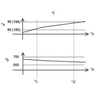
- If the automatic transaxle fluid temperature tends to decrease when the automatic transaxle fluid temperature is between 85°C (185°F) and 90°C (194°F) with the engine idling, make sure that automatic transaxle fluid temperature is above 90°C (194°F) before starting work.
- If the automatic transaxle fluid temperature tends to increase when the automatic transaxle fluid temperature is between 85°C (185°F) and 90°C (194°F) with the engine idling, make sure that automatic transaxle fluid temperature is below 85°C (185°F) before starting work.
- If the automatic transaxle fluid temperature tends not to change when the automatic transaxle fluid temperature is between 85°C (185°F) and 90°C (194°F) with the engine idling, make sure that automatic transaxle fluid temperature is 87.5°C (189.5°F) before starting work.
(h) Depress and hold the brake pedal.
(i) Start the engine.
(j) Slowly move the shift lever from P to D, and then back to P.
(k) Lift the vehicle.
NOTICE:
Set the vehicle on a lift so that the vehicle is kept level when it is lifted up (make sure the tilt angle from the front to rear and side to side of the vehicle is within +/- 1°).
(l) Remove the No. 2 engine under cover.
(m) Remove the front fender apron LH.
(n) When using the WS ATF level gauge system:
|
(1) Remove the refill plug and gasket from the rear transaxle cover sub-assembly. |
|
|
(2) Install the transmission fill adapter to the refill hole. |
|
|
(3) Connect the vacuum regulator manifold to the transmission fill adapter. |
|
|
(4) Connect the fluid extraction tank hose to the vacuum regulator manifold. NOTICE: Ensure both of the fluid extraction tank valves are off by turning each valve handle so it is perpendicular to the hose. |
|
(5) Connect a compressed air hose to the fluid extraction tank.
CAUTION:
Do not apply 689 kPa (7.03 kgf/cm2, 100 psi) or more of compressed air at to the fluid extraction tank.
|
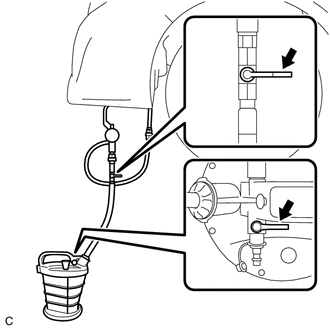
(6) Open the fluid extraction tank lower valve by turning the handle so it is in-line with the hose. |
|
|
(7) Open the fluid extraction tank upper valve by turning the handle so it is in-line with the hose. NOTICE: Make sure the value on the vacuum regulator manifold gauge stays between 2 - 5 in. Hg (10 - 20 kPa). HINT: Vacuum will be applied to the transaxle when both of the fluid extraction tank valves are opened to prevent automatic transaxle fluid loss when removing/installing the overflow plug. |
|
|
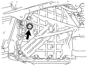
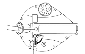
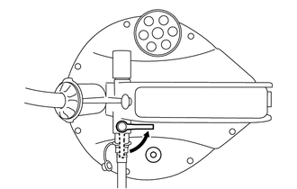
(8) Using a 6 mm hexagon socket wrench, remove the overflow plug and gasket from the automatic transaxle oil pan sub-assembly. CAUTION: A small amount of HOT automatic transaxle fluid may leak from the overflow plug hole during removal. HINT: Place an oil drain pan under the overflow plug hole to collect any automatic transaxle fluid. |
|
.png)
|
(9) Install a 12 mm adapter to the WS ATF level gauge and then install the WS ATF level gauge to the overflow plug hole by hand until it is fully seated against the automatic transaxle oil pan sub-assembly. NOTICE: Ensure that the sliding tube is fully retracted into the WS ATF level gauge housing before inserting it into the overflow plug hole. HINT: The level/measurement indicator on the WS ATF level gauge will read 0 mm when the sliding tube is fully retracted. |
|
(10) Adjust the WS ATF level gauge to the correct measurement according to the table below and lock the sliding scale by tightening the thumb screw.
Specified Measurement:|
Specified Measurement at Automatic Transaxle Fluid Temperature of 85°C (185°F) to 90°C (194°F) |
|
|
Engine Idle Speed: 600 to 700 rpm |
75.5 mm (2.97 in.) |
|
Engine Idle Speed: 700 to 800 rpm |
72.0 mm (2.83 in.) |
NOTICE:
Before proceeding with the inspection, make sure the automatic transaxle fluid temperature is between 85°C (185°F) to 90°C (194°F) and the engine idle speed is within the specified range in the table above.
|
(11) Close the fluid extraction tank upper valve by turning the handle so it is perpendicular to the hose. HINT: Vacuum will not be applied when either fluid extraction tank valve is closed. Make sure that the vacuum gauge reads 0 in. Hg (0 kPa). |
|
(12) Observe automatic transaxle fluid flowing from the hose at the bottom of the WS ATF level gauge.
NOTICE:
- If the automatic transaxle fluid flows out slowly or only drips, the automatic transaxle fluid level is within specification.
- If the automatic transaxle fluid flows out rapidly, allow the excess automatic transaxle fluid to drain until only drips come out.
- If no automatic transaxle fluid flows out, add automatic transaxle fluid to the refill hole until it comes out of the overflow plug hole. Wait until the automatic transaxle fluid flow slows and only drips come out (refer to Fluid Level Adjustment Procedure).
(13) Confirm that the automatic transaxle fluid is at the specified level.
|
(14) Open the fluid extraction tank upper valve by turning the handle so it is in-line with the hose. NOTICE: Make sure the value on the vacuum regulator manifold gauge stays between 2 - 5 in. Hg (10 - 20 kPa) before proceeding to the next step. HINT: Vacuum will be applied to the transaxle when both of the fluid extraction tank valves are opened to prevent automatic transaxle fluid loss when removing/installing the overflow plug. |
|
(15) Remove the WS ATF level gauge from the overflow plug hole.
(16) Install the overflow plug and a new gasket to the automatic transaxle oil pan sub-assembly.
Torque:
40 N·m {408 kgf·cm, 30 ft·lbf}
|
(17) Close the fluid extraction tank upper valve by turning the handle so it is perpendicular to the hose. HINT: Vacuum will not be applied when either fluid extraction tank valve is closed. Make sure that the vacuum gauge reads 0 in. Hg (0 kPa). |
|
|
(18) Close the fluid extraction tank lower valve by turning the handle so it is perpendicular to the hose. |
|
(19) Disconnect the compressed air hose from the fluid extraction tank.
(20) Disconnect the fluid extraction tank hose from the vacuum regulator manifold.
(21) Disconnect the vacuum regulator manifold from the transmission fill adapter.
(22) Remove the transmission fill adapter from the refill hole.
(o) When not using the WS ATF level gauge system:
|
(1) Loosen the refill plug. |
|
|
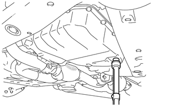
(2) Using a 6 mm hexagon socket wrench, remove the overflow plug and gasket from the automatic transaxle assembly. [*1] CAUTION: Be careful as the automatic transaxle fluid coming out of the overflow plug hole is hot. NOTICE:
|
|
|
(3) Make sure that the automatic transaxle fluid temperature and engine speed remain within the appropriate range until the overflow plug is tightened in step [*2]. Text in Illustration
|
|
|
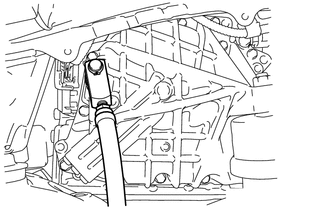
(4) Wait until the automatic transaxle fluid flow slows and only drips come out. HINT: If the automatic transaxle fluid temperature is increasing, the automatic transaxle fluid flow will not completely stop because the automatic transaxle fluid expands as its temperature increases. |
|
.png)
|
(5) Using a 6 mm hexagon socket wrench, install the overflow plug and a new gasket to the automatic transaxle assembly. [*2] Torque: 40 N·m {408 kgf·cm, 30 ft·lbf} |
|
(6) Lower the vehicle.
(7) Turn the ignition switch off.
|
(8) Remove the refill plug and gasket from the rear transaxle cover sub-assembly. |
|
|
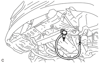
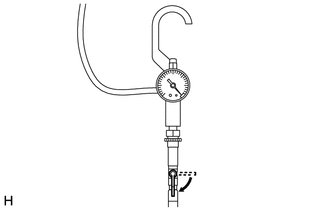
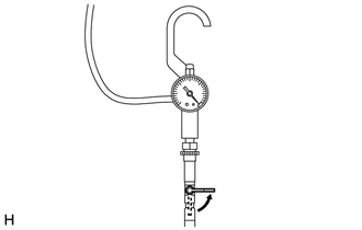
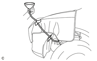
(9) Install a hose and funnel to the refill hole as shown in the illustration. NOTICE:
HINT: Make sure to use a hose with a length of 1250 mm (4.1 ft.) and an outer diameter of 16 mm (0.63 in.). |
|
(10) Add the specified amount of automatic transaxle fluid to the refill hole. [*3]
If determining the specific amount of automatic transaxle fluid to be added, refer to the table below.
Specified Amount to be Added (Automatic Transaxle Fluid Weight):|
Specified Amount to be Added at Automatic Transaxle Fluid Temperature of 85°C (185°F) to 90°C (194°F) |
|
|
Engine Idle Speed: 600 to 700 rpm |
460 g (16.2 oz) 550 cc (33.6 cu. in.) |
|
Engine Idle Speed: 700 to 800 rpm |
420 g (14.8 oz) 500 cc (30.5 cu. in.) |
NOTICE:
- If automatic transaxle fluid remains inside the hose, the amount of automatic transaxle fluid will be outside the specification. Therefore, when adding automatic transaxle fluid, make sure that no automatic transaxle fluid remains inside the hose.
- The acceptable margin of error when adding automatic transaxle fluid is +/- 20 g (0.7 oz) or +/- 25 cc (1.5 cu. in.).
- Use Toyota Genuine ATF WS.
HINT:
- The values in the table are reference values for when the temperature of the automatic transaxle fluid to be added is between 10°C (50°F) and 30°C (86°F).
- If automatic transaxle fluid comes out (the amount of automatic transaxle fluid is not as specified), perform the procedure from step [*4] again.
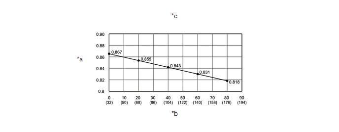
If determining the specified amount of automatic transaxle fluid to be added by volume, calculate it based on weight and density at each temperature.
 Text in Illustration
|
*a |
Density [g / cc] |
*b |
Temperature of automatic transaxle fluid to be measured [°C (°F)] |
|
*c |
Relation between temperature and density of Toyota genuine ATF WS |
- |
- |
|
(11) Install the refill plug and a new gasket to the rear transaxle cover sub-assembly. Torque: 49 N·m {500 kgf·cm, 36 ft·lbf} |
|
(12) Disconnect the Techstream from the DLC3.
2. REBUILD WORK
(a) Lift the vehicle.
(b) Clean each part.
(c) Check for fluid leaks.
(d) Install the front fender apron LH.
(e) Install the No. 2 engine under cover.
(f) Lower the vehicle.
 Adjustment
ADJUSTMENT
PROCEDURE
1. PRECAUTIONS AND WORK DESCRIPTION
(a) The U660E automatic transaxle does not have an oil filler tube and oil level
gauge. When adding fluid, add fluid through the refill ho ...

Other materials about Toyota Venza:
Portable Player cannot be Operated Using In-vehicle Device or Track Information
is not Displayed on In-vehicle Device
PROCEDURE
1.
CHECK USING ANOTHER "Bluetooth" AUDIO COMPATIBLE VEHICLE OF SAME MODEL
(a) Check if track information is displayed normally on another "Bluetooth" audio
compatible vehicle of the same model.
...
Registration
REGISTRATION
PROCEDURE
1. REGISTER TRANSMITTER CODE
HINT:
The vehicles garage door opener system records transmitter codes for
systems such as garage doors, gates, door locks, home lighting systems,
security systems or other transmitter-cod ...
No Answer-Back
DESCRIPTION
In some cases, wireless door lock control functions are normal but the hazard
warning light and/or wireless door lock buzzer answer-back function(s) does not
operate. In such cases, the main body ECU (driver side junction block assembly)
haz ...

0.1557