Toyota Venza: Power Seat Power Easy Access System Function does not Operate
DESCRIPTION
When the ignition switch is off and shift lever is in P, the power seat slides rearward when the seat belt tongue plate is disengaged from the front seat inner belt assembly LH (auto away function). Also the power seat slides forward when the seat belt tongue plate is engaged to the front seat inner belt assembly LH with the ignition switch ACC or ON, and shift lever is in P.
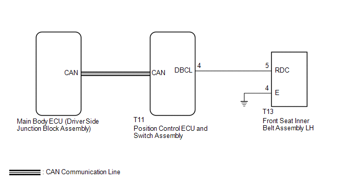
WIRING DIAGRAM
CAUTION / NOTICE / HINT
NOTICE:
The front power seat control system (w/ Memory) uses the CAN communication system.
First, confirm that there is no malfunction in the communication system by checking
communication function of the CAN communication system. Refer to the How to Proceed
with Troubleshooting procedure (See page .gif) ).
).
PROCEDURE
|
1. |
CHECK FRONT POWER SEAT OPERATION |
(a) Check that each function of the power seat operates normally by using the
position control ECU and switch assembly (See page
).
|
Result |
Proceed to |
|---|---|
|
Power seat functions operate normally |
A |
|
All power seat functions do not operate |
B |
|
One or more power seat motors do not operate |
C |
| B | .gif) |
GO TO OTHER DIAGNOSIS PROCEDURE (Front Power Seat does not Operate with Front Power Seat Switch) |
| C | |
GO TO OTHER DIAGNOSIS PROCEDURE (One or more Power Seat Motors do not Operate) |
|
.gif)
|
2. |
READ VALUE USING TECHSTREAM |
(a) Connect the Techstream to the DLC3.
(b) Turn the ignition switch to ON.
(c) Turn the Techstream on.
(d) Enter the following menus: Body Electrical / Driver Seat / Data List.
(e) Read the Data List according to the display on the Techstream.
Driver Seat|
Tester Display |
Measurement Item/Range |
Normal Condition |
Diagnostic Note |
|---|---|---|---|
|
Driver Seat Buckle SW |
Driver seat belt buckle switch / ON or OFF |
ON: Driver seat belt fastened OFF: Driver seat belt unfastened |
- |
OK:
On the Techstream screen, the item changes between ON and OFF according to the above.
| NG | |
GO TO STEP 5 |
|
|
3. |
REPLACE POSITION CONTROL ECU AND SWITCH ASSEMBLY |
(a) Replace the position control ECU and switch assembly (See page
).
|
|
4. |
CHECK POWER SEAT POWER EASY ACCESS SYSTEM |
(a) Check that the power seat easy access system operates normally when engaging
and disengaging the tongue plate of the seat belt with the shift lever in P (See
page ).
OK:
Power seat power easy access system is normal.
| OK | |
END (POSITION CONTROL ECU AND SWITCH ASSEMBLY WAS DEFECTIVE) |
| NG | |
REPLACE MAIN BODY ECU (DRIVER SIDE JUNCTION BLOCK ASSEMBLY) |
|
5. |
INSPECT FRONT SEAT INNER BELT ASSEMBLY LH |
|
(a) Remove the front seat inner belt assembly LH (See page
|
|
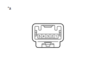
(b) Measure the resistance according to the value(s) in the table below.
Standard Resistance:
|
Tester Connection |
Condition |
Specified Condition |
|---|---|---|
|
4 - 5 |
Driver seat belt unfastened |
10 kΩ or higher |
|
4 - 5 |
Driver seat belt fastened |
Below 1 Ω |
|
*a |
Component without harness connected (Front Seat Inner Belt Assembly LH) |
| NG | |
REPLACE FRONT SEAT INNER BELT ASSEMBLY LH |
|
|
6. |
CHECK HARNESS AND CONNECTOR (POSITION CONTROL ECU AND SWITCH ASSEMBLY - FRONT SEAT INNER BELT ASSEMBLY LH) |
(a) Disconnect the T11 the position control ECU and switch assembly connector.
(b) Measure the resistance according to the value(s) in the table below.
Standard Resistance:
|
Tester Connection |
Condition |
Specified Condition |
|---|---|---|
|
T11-4 (DBCL) - T13-5 (RDC) |
Always |
Below 1 Ω |
|
T13-4 (E) - Body ground |
Always |
Below 1 Ω |
|
T11-4 (DBCL) - Body ground |
Always |
10 kΩ or higher |
| OK | |
REPLACE POSITION CONTROL ECU AND SWITCH ASSEMBLY |
| NG | |
REPAIR OR REPLACE HARNESS OR CONNECTOR |
 Wireless-linked Return Function does not Operate
DESCRIPTION
When a door is unlocked using the wireless unlock function or entry unlock function,
the certification ECU (smart key ECU assembly) sends a door unlock signal and key
ID signal to the ...

Other materials about Toyota Venza:
Disposal
DISPOSAL
CAUTION / NOTICE / HINT
CAUTION:
Before performing pre-disposal deployment of any SRS part, review and closely
follow all applicable environmental and hazardous material regulations. Pre-disposal
deployment may be considered hazardous material ...
Rear Right Center Sensor Malfunction (C1AE8)
DESCRIPTION
The No. 1 ultrasonic sensor (rear right center sensor) is installed on the rear
bumper. The ECU detects obstacles based on signals received from the No. 1 ultrasonic
sensor (rear right center sensor). If the No. 1 ultrasonic sensor (rear right ...
Installation
INSTALLATION
CAUTION / NOTICE / HINT
HINT:
Use the same procedure for the LH side and RH side.
The following procedure listed is for the LH side.
PROCEDURE
1. INSTALL FRONT LOWER BALL JOINT
(a) Install the front lower ball jo ...

0.1539