Toyota Venza: Headlight Dimmer Switch
Components
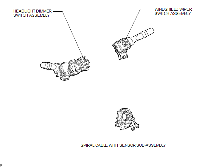
COMPONENTS
ILLUSTRATION
Removal
REMOVAL
PROCEDURE
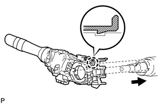
1. REMOVE SPIRAL CABLE WITH SENSOR SUB-ASSEMBLY
(See page .gif) )
)
2. REMOVE WINDSHIELD WIPER SWITCH ASSEMBLY
3. REMOVE HEADLIGHT DIMMER SWITCH ASSEMBLY
|
(a) Disconnect the connector. |
|
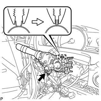
(b) Disengage the clamp as shown in the illustration.
|
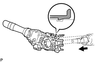
(c) Disengage the claw and remove the headlight dimmer switch assembly as shown in the illustration. |
|
Inspection
INSPECTION
PROCEDURE
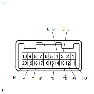
1. INSPECT HEADLIGHT DIMMER SWITCH ASSEMBLY
|
(a) Measure the resistance according to the value(s) in the table below. Standard Resistance: Light Control Switch
If the result is not as specified, replace the headlight dimmer switch assembly. |
|
Installation
INSTALLATION
PROCEDURE
1. INSTALL HEADLIGHT DIMMER SWITCH ASSEMBLY
|
(a) Install the headlight dimmer switch assembly as shown in the illustration. |
|
(b) Engage the claw.
|
(c) Install the headlight dimmer switch assembly with the clamp. |
|

(d) Connect the connector.
2. INSTALL WINDSHIELD WIPER SWITCH ASSEMBLY
.gif)
3. INSTALL SPIRAL CABLE WITH SENSOR SUB-ASSEMBLY
(See page )
 Installation
INSTALLATION
PROCEDURE
1. INSTALL HEADLIGHT ASSEMBLY
(a) Connect each connector.
(b) Install the headlight assembly with the bolt and 3 screws.
Torque:
3.6 N·m {37 kgf·cm, 32 in·lbf}
2. INS ...
 Headlight Leveling Ecu
Components
COMPONENTS
ILLUSTRATION
Removal
REMOVAL
PROCEDURE
1. REMOVE HEADLIGHT LEVELING ECU ASSEMBLY
(a) Disconnect the connector.
...
Other materials about Toyota Venza:
On-vehicle Inspection
ON-VEHICLE INSPECTION
CAUTION / NOTICE / HINT
HINT:
Use the same procedure for the RH side and LH side.
The procedure listed below is for the LH side.
PROCEDURE
1. REMOVE FRONT WHEEL
2. SEPARATE FRONT DISC BRAKE CALIPER ASSEMBLY
3. ...
Lost Communication with ECM / PCM "A" (U0100)
DESCRIPTION
The engine control unit communicates with the TCM using the Controller Area Network
(CAN).
If there is a problem in this communication, the TCM sets a DTC.
DTC No.
DTC Detection Condition
Trouble Area
...
Satellite Radio Broadcast cannot be Selected or After Selecting Broadcast, Broadcast
cannot be Added into Memory
CAUTION / NOTICE / HINT
NOTICE:
Some satellite radio broadcasts require payment. A contract must be made between
a satellite radio company and the user. If the contract expires, it will not be
possible to listen to the broadcast.
PROCEDURE
1 ...

0.1565