Toyota Venza: Back Door Entry Unlock Function does not Operate
DESCRIPTION
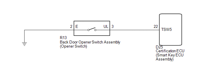
If the entry back door open function does not operate but the back door entry lock function operates, the communication between the vehicle and key is normal. As a faulty part, the back door open switch circuit (from the back door opener switch assembly (opener switch) to the certification ECU (smart key ECU assembly)) is suspected.
WIRING DIAGRAM
CAUTION / NOTICE / HINT
NOTICE:
- The smart key system (for entry function) uses a multiplex communication
system (LIN communication system) and CAN communication system. Inspect
the communication function by following How to Proceed with Troubleshooting
(See page
.gif) ). Troubleshoot the smart
). Troubleshoot the smart
key system (for entry function) after confirming that the communication system is functioning properly. - Confirm that another key is not in the cabin.
PROCEDURE
|
1. |
READ VALUE USING TECHSTREAM (ENTRY BACK DOOR OPEN FUNCTION) |
(a) Connect the Techstream to the DLC3.
(b) Turn the engine switch on (IG).
(c) Turn the Techstream on.
(d) Enter the following menus: Body Electrical / Smart Key / Data List.
(e) Read the Data List according to the display on the Techstream.
Smart Key (Certification ECU (Smart Key ECU Assembly))|
Tester Display |
Measurement Item/Range |
Normal Condition |
Diagnostic Note |
|---|---|---|---|
|
B-Dr Opening Operation |
Back door opening Operation / Long, Twice, OFF |
Customization status displayed |
- |
|
Result |
Proceed to |
|---|---|
|
Customize setting is LONG or TWICE. |
A |
|
Customize setting is OFF. |
B |
| B | .gif) |
PERFORM CUSTOMIZE SETTING (Proceed to Customize Parameters) |
|
.gif)
|
2. |
CHECK POWER DOOR LOCK CONTROL SYSTEM |
(a) When the door control switch on the master switch assembly is operated, check
that the doors unlock and lock according to switch operation (See page
).
OK:
Door locks operate normally.
| NG | |
GO TO POWER DOOR LOCK CONTROL SYSTEM (Proceed to Problem Symptoms Table) |
|
|
3. |
READ VALUE USING TECHSTREAM (BACK DOOR OPENER SWITCH) |
(a) Connect the Techstream to the DLC3.
(b) Turn the engine switch on (IG).
(c) Turn the Techstream on.
(d) Enter the following menus: Body Electrical / Smart Key / Data List.
(e) Read the Data List according to the display on the Techstream.
Smart Key (Certification ECU (Smart Key ECU Assembly))|
Tester Display |
Measurement Item/Range |
Normal Condition |
Diagnostic Note |
|---|---|---|---|
|
Tr/B-Door Unlock SW |
Back door opener switch assembly (opener switch) / ON or OFF |
ON: Back door opener switch assembly (opener switch) pushed OFF: Back door opener switch assembly (opener switch) not pushed |
- |
OK:
On the Techstream screen, the display changes between ON and OFF as shown in the chart above.
| OK | |
REPLACE CERTIFICATION ECU (SMART KEY ECU ASSEMBLY) |
|
|
4. |
INSPECT BACK DOOR OPENER SWITCH ASSEMBLY |
|
(a) Remove the back door opener switch assembly (See page
|
|
(b) Measure the resistance according to the value(s) in the table below.
Standard Resistance:
|
Tester Connection |
Switch Position |
Specified Condition |
|---|---|---|
|
2 (E) - 3 (UL) |
Back door opener switch assembly (opener switch) not pushed (OFF) |
10 kΩ or higher |
|
2 (E) - 3 (UL) |
Back door opener switch assembly (opener switch) pushed (ON) |
Below 1 Ω |
|
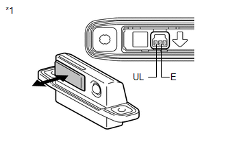
*1 |
Component without harness connected (Back Door Opener Switch Assembly) |
| NG | |
REPLACE BACK DOOR OPENER SWITCH ASSEMBLY |
|
|
5. |
CHECK HARNESS AND CONNECTOR (CERTIFICATION ECU - BACK DOOR OPENER SWITCH) |
|
(a) Disconnect the certification ECU (smart key ECU Assembly) connector. |
|
(b) Measure the resistance according to the value(s) in the table below.
Standard Resistance:
|
Tester Connection |
Condition |
Specified Condition |
|---|---|---|
|
D25-22 (TSW5) - R13-3 (UL) |
Always |
Below 1 Ω |
|
D25-22 (TSW5) - Body ground |
Always |
10 kΩ or higher |
|
R13-3 (UL) - Body ground |
Always |
10 kΩ or higher |
|
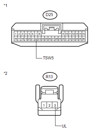
*1 |
Front view of wire harness connector (to Certification ECU (Smart Key ECU Assembly)) |
|
*2 |
Front view of wire harness connector (to Back Door Opener Switch Assembly) |
| OK | |
REPLACE CERTIFICATION ECU (SMART KEY ECU ASSEMBLY) |
| NG | |
REPAIR OR REPLACE HARNESS OR CONNECTOR |
 Entry Interior Alarm does not Sound
DESCRIPTION
The smart key system uses the combination meter buzzer to perform various vehicle
interior warnings. When the conditions for each warning are met, the certification
ECU (smart key ECU ...
 Back Door Entry Lock and Unlock Functions do not Operate
DESCRIPTION
When the back door entry lock and unlock functions do not operate, one of the
following may be malfunctioning: 1) power door lock control system; 2) outside electrical
key oscillator ...
Other materials about Toyota Venza:
Repair
REPAIR
PROCEDURE
1. REPAIR INTAKE VALVE SEAT
NOTICE:
Repair the seat while checking the seating position.
Keep the lip free of foreign matter.
Take off the cutter gradually to make the intake valve seat smooth.
(a) Usin ...
System Description
SYSTEM DESCRIPTION
1. FRONT POWER SEAT CONTROL SYSTEM DESCRIPTION
The driver seat is equipped with slide, reclining, lifter, front vertical,
and lumbar support adjustment functions.
The memory call function uses the key ID code of the key to m ...
Registering ID codes
The tire pressure warning valve and transmitter is equipped with a unique ID
code. When replacing a tire pressure warning valve and transmitter, it is necessary
to register the ID code of tire pressure warning valve and transmitter. Have the
ID code regi ...

0.1566