Toyota Venza: Electrical Key Oscillator(for Rear Floor)
Components
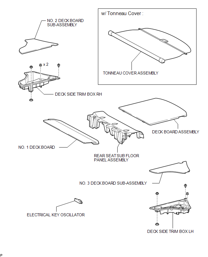
COMPONENTS
ILLUSTRATION
Removal
REMOVAL
PROCEDURE
1. REMOVE TONNEAU COVER ASSEMBLY (w/ Tonneau Cover)
.gif)
2. REMOVE DECK BOARD ASSEMBLY
3. REMOVE NO. 3 DECK BOARD SUB-ASSEMBLY
4. REMOVE DECK SIDE TRIM BOX LH
5. REMOVE NO. 2 DECK BOARD SUB-ASSEMBLY
6. REMOVE DECK SIDE TRIM BOX RH
7. REMOVE NO. 1 DECK BOARD
8. REMOVE REAR SEAT SUB FLOOR PANEL ASSEMBLY
9. REMOVE ELECTRICAL KEY OSCILLATOR
|
(a) Disconnect the connector. |
|
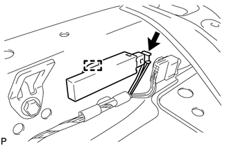
(b) Disengage the clamp and remove the electrical key oscillator.
NOTICE:
Be careful when removing the electrical key oscillator. If the oscillator is dropped, replace it with a new one.
Installation
INSTALLATION
PROCEDURE
1. INSTALL ELECTRICAL KEY OSCILLATOR
|
(a) Engage the clamp and install the electrical key oscillator. NOTICE: Be careful when installing the electrical key oscillator. If the oscillator is dropped, replace it with a new one. |
|
.png)
(b) Connect the connector.
2. INSTALL REAR SEAT SUB FLOOR PANEL ASSEMBLY
.gif)
3. INSTALL NO. 1 DECK BOARD
4. INSTALL DECK SIDE TRIM BOX RH
5. INSTALL NO. 2 DECK BOARD SUB-ASSEMBLY
6. INSTALL DECK SIDE TRIM BOX LH
7. INSTALL NO. 3 DECK BOARD SUB-ASSEMBLY
8. INSTALL DECK BOARD ASSEMBLY
9. INSTALL TONNEAU COVER ASSEMBLY (w/ Tonneau Cover)
 Electrical Key Oscillator(for Front Floor)
Components
COMPONENTS
ILLUSTRATION
Installation
INSTALLATION
PROCEDURE
1. INSTALL ELECTRICAL KEY OSCILLATOR
(a) Engage the clamp and install the electrical key oscillator.
N ...
 Electrical Key Oscillator(for Rear Side)
Components
COMPONENTS
ILLUSTRATION
Removal
REMOVAL
PROCEDURE
1. REMOVE REAR BUMPER PLATE LH
2. REMOVE REAR BUMPER PLATE RH
3. REMOVE REAR BUMPER ASSEMBLY
4. REMOVE ELECTRICAL K ...
Other materials about Toyota Venza:
Noise Occurs
PROCEDURE
1.
CHECK NOISE CONDITION
(a) Check from which direction the noise comes (front left or right, or rear
left or right).
OK:
The location of the noise source can be determined.
NG
GO TO STEP 3
...
Multi-information display (LCD type)
The multi-information display presents the driver with a variety of driving-related
data, including the clock and current outside temperature.
• Clock
Indicates and sets the time.
• Outside temperature
Indicates the outside temperature.
The temper ...
How To Proceed With Troubleshooting
CAUTION / NOTICE / HINT
HINT:
Use the following procedure to troubleshoot the lighting system.
*: Use the Techstream.
PROCEDURE
1.
VEHICLE BROUGHT TO WORKSHOP
NEXT
...

0.2112