Toyota Venza: Electrical Key Oscillator(for Front Floor)
Components
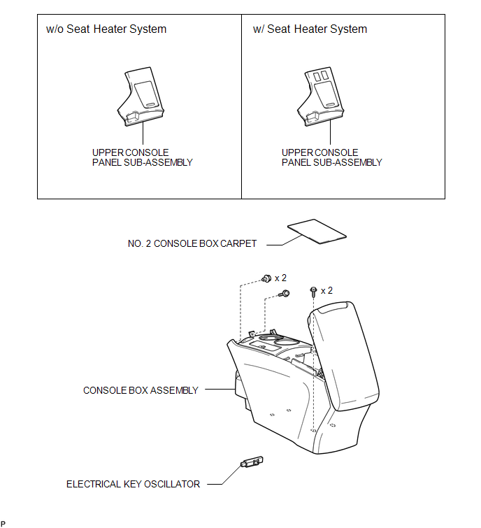
COMPONENTS
ILLUSTRATION
Installation
INSTALLATION
PROCEDURE
1. INSTALL ELECTRICAL KEY OSCILLATOR
|
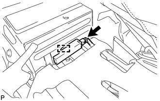
(a) Engage the clamp and install the electrical key oscillator. NOTICE: Be careful when installing the electrical key oscillator. If the oscillator is dropped, replace it with a new one. |
|
(b) Connect the connector.
2. INSTALL CONSOLE BOX ASSEMBLY
.gif)
3. INSTALL NO. 2 CONSOLE BOX CARPET
4. INSTALL UPPER CONSOLE PANEL SUB-ASSEMBLY (w/o Seat Heater System)
5. INSTALL UPPER CONSOLE PANEL SUB-ASSEMBLY (w/ Seat Heater System)
Removal
REMOVAL
PROCEDURE
1. REMOVE UPPER CONSOLE PANEL SUB-ASSEMBLY (w/o Seat Heater System)
.gif)
2. REMOVE UPPER CONSOLE PANEL SUB-ASSEMBLY (w/ Seat Heater System)
3. REMOVE NO. 2 CONSOLE BOX CARPET
4. REMOVE CONSOLE BOX ASSEMBLY
5. REMOVE ELECTRICAL KEY OSCILLATOR
|
(a) Disconnect the connector. |
|
.png)
(b) Disengage the clamp and remove the electrical key oscillator.
NOTICE:
Be careful when removing the electrical key oscillator. If the oscillator is dropped, replace it with a new one.
 Electrical Key Oscillator(for Center Floor)
Components
COMPONENTS
ILLUSTRATION
Installation
INSTALLATION
PROCEDURE
1. INSTALL ELECTRICAL KEY OSCILLATOR
(a) Engage the clamp and install the electrical key oscillator.
N ...
 Electrical Key Oscillator(for Rear Floor)
Components
COMPONENTS
ILLUSTRATION
Removal
REMOVAL
PROCEDURE
1. REMOVE TONNEAU COVER ASSEMBLY (w/ Tonneau Cover)
2. REMOVE DECK BOARD ASSEMBLY
3. REMOVE NO. 3 DECK BOARD SUB-ASSEMB ...
Other materials about Toyota Venza:
Removal
REMOVAL
CAUTION / NOTICE / HINT
HINT:
Use the same procedure for the RH side and LH side.
The procedure listed below is for the LH side.
PROCEDURE
1. PRECAUTION
CAUTION:
Be sure to read Precaution thoroughly before servicing (See page
...
If a warning message is displayed
The multi-information display shows warnings of system malfunctions or incorrectly
performed operations. When a message is shown, perform corrections as indicated
in the message.
1. Master warning light
The master warning light comes on or flashes when ...
Diagnosis System
DIAGNOSIS SYSTEM
1. DESCRIPTION
(a) Diagnostic Trouble Codes (DTCs) can be read from the Data Link Connector
3 (DLC3) of the vehicle. When the rear view monitor system seems to be malfunctioning,
use the Techstream to check for malfunctions and to perfor ...

0.1288