Toyota Venza: Driver Side Seat Belt Warning Light does not Operate
DESCRIPTION
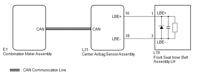
When the ignition switch is ON, the center airbag sensor assembly transmits front seat inner belt status signals to the combination meter assembly through CAN. If the driver seat belt is not fastened, the combination meter assembly blinks the driver side seat belt warning light. If the seat belt is fastened, the warning light goes off.
WIRING DIAGRAM
CAUTION / NOTICE / HINT
NOTICE:
The seat belt warning system uses the CAN communication system. First, confirm
that there is no malfunction in the CAN communication system. Refer to the How to
Proceed with Troubleshooting procedure (See page
.gif) ).
).
PROCEDURE
|
1. |
CHECK DTC OUTPUT (CAN COMMUNICATION SYSTEM) |
(a) Clear the DTC (See page ).
(b) Recheck for DTCs.
|
Result |
Proceed to |
|---|---|
|
DTC is not output |
A |
|
DTC is output |
B |
| B | .gif) |
GO TO CAN COMMUNICATION SYSTEM |
|
.gif)
|
2. |
CHECK DTC OUTPUT (AIRBAG SYSTEM) |
(a) Clear the DTC (See page ).
(b) Recheck for DTCs.
|
Result |
Proceed to |
|---|---|
|
DTC is not output |
A |
|
DTC is output |
B |
| B | |
GO TO AIRBAG SYSTEM |
|
|
3. |
PERFORM ACTIVE TEST USING TECHSTREAM |
(a) Connect the Techstream to the DLC3.
(b) Turn the ignition switch to ON.
(c) Turn the Techstream on.
(d) Enter the following menus: Body Electrical / Combination Meter / Active Test.
(e) Perform the Active Test according to the display on the Techstream.
Combination Meter (Combination Meter Assembly)|
Tester Display |
Test Part |
Control Range |
Diagnostic Note |
|---|---|---|---|
|
Driver Side Seat Belt |
Driver side seat belt warning light |
OFF or ON |
Confirm that the vehicle stopped with the engine idling |
OK:
The driver side seat belt warning light on the combination meter assembly operates normally.
| OK | |
USE SIMULATION METHOD TO CHECK |
| NG | |
REPLACE COMBINATION METER ASSEMBLY |
 Data List / Active Test
DATA LIST / ACTIVE TEST
1. DATA LIST
HINT:
Using the Techstream to read the Data List allows the values or states of switches,
sensors, actuators and other items to be read without removing any p ...
 On-vehicle Inspection
ON-VEHICLE INSPECTION
PROCEDURE
1. INSPECT DRIVER SIDE SEAT BELT WARNING
(a) Turn the ignition switch to ON.
(b) When the driver side seat belt is not fastened, check that the driver side
seat b ...
Other materials about Toyota Venza:
Wireless Transmitter Memory Function does not Operate
DESCRIPTION
Key IDs can be registered (linked) with either the M1 or M2 seat memory switches.
The key ID registration procedure should be performed while the electrical key transmitter
sub-assembly or door control transmitter assembly is in the vehicle, t ...
Problem Symptoms Table
PROBLEM SYMPTOMS TABLE
HINT:
Use the table below to help determine the cause of problem symptoms.
If multiple suspected areas are listed, the potential causes of the symptoms
are listed in order of probability in the "Suspected Area" ...
Wireless Transmitter Memory Function does not Operate
DESCRIPTION
With the ignition switch off and the driver door closed, pressing the manual
lock or unlock switch on the power window regulator master switch assembly while
holding a seat memory switch (M1 switch or M2 switch) will register the transmitter
...

0.1134