Toyota Venza: Drive Belt
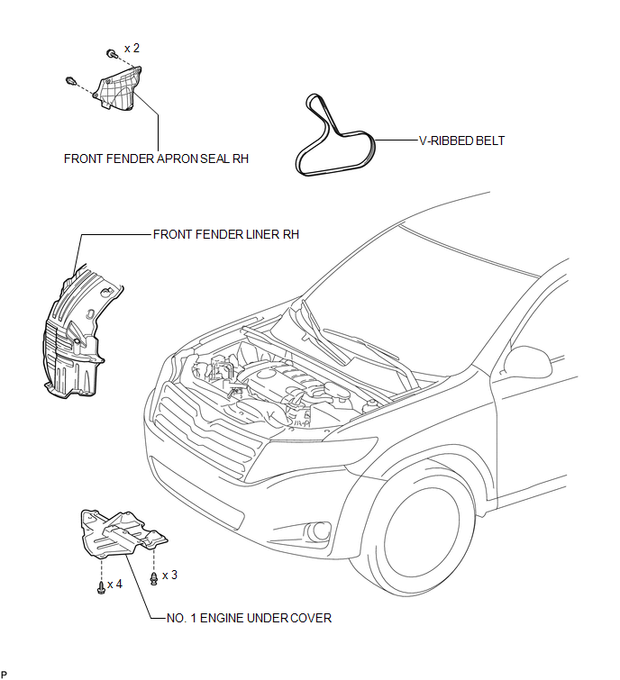
Components
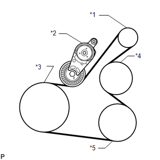
COMPONENTS
ILLUSTRATION
On-vehicle Inspection
ON-VEHICLE INSPECTION
PROCEDURE
1. INSPECT V-RIBBED BELT
|
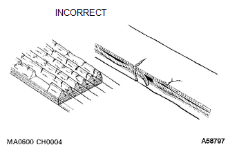
(a) Check the belt for wear, cracks or other signs of damage. If any of the following defects is found, replace the V-ribbed belt.
|
|
|
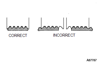
(b) Check that the belt fits properly in the ribbed grooves. HINT: Check with your hand to confirm that the belt has not slipped out of the groove on the bottom of the pulley. If it has slipped out, replace the V-ribbed belt. Install a new V-ribbed belt correctly. |
|
2. INSPECT V-RIBBED BELT TENSIONER ASSEMBLY
(a) Check that nothing gets caught in the tensioner by turning it clockwise and counterclockwise.
If a malfunction exists, replace the V-ribbed belt tensioner.
Removal
REMOVAL
PROCEDURE
1. REMOVE FRONT WHEEL RH
2. REMOVE NO. 1 ENGINE UNDER COVER
3. SEPARATE FRONT FENDER LINER RH
4. REMOVE FRONT FENDER APRON SEAL RH
.gif)
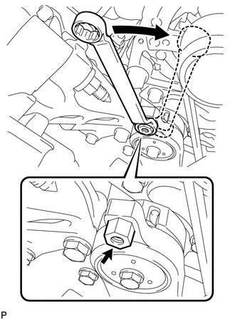
5. REMOVE V-RIBBED BELT
|
(a) Attach a wrench to the hexagonal portion of the belt tensioner as shown in the illustration, rotate the belt tensioner clockwise, and remove the V-ribbed belt. |
|
Installation
INSTALLATION
PROCEDURE
1. INSTALL V-RIBBED BELT
|
(a) Set the V-ribbed belt onto each part as shown in the illustration except the water pump pulley. Text in Illustration
|
|
(b) Loosen the V-ribbed belt by turning the belt tensioner clockwise.
(c) Set the V-ribbed belt onto the water pump pulley.
NOTICE:
Make sure that the belt is attached to each pulley. In particular, make sure that the belt is securely fitted into the grooves of the crankshaft pulley.
2. INSTALL FRONT FENDER APRON SEAL RH
.gif)
3. INSTALL FRONT FENDER LINER RH
4. INSTALL NO. 1 ENGINE UNDER COVER
5. INSTALL FRONT WHEEL RH
Torque:
103 N·m {1050 kgf·cm, 76 ft·lbf}
 Installation
INSTALLATION
CAUTION / NOTICE / HINT
HINT:
Perform "Inspection After Repair" after replacing the camshaft, No. 2 camshaft,
camshaft timing gear assembly, camshaft timing exhaust gear as ...
 Engine
...
Other materials about Toyota Venza:
Installation
INSTALLATION
PROCEDURE
1. INSTALL MANUAL VALVE
(a) Coat the manual valve with ATF and install it to the transmission valve body
assembly.
2. SUPPORT ENGINE ASSEMBLY
3. INSTALL TRANSMISSION VALVE BODY ASSEMBLY
(a) Coat the O-ring of the transmission ...
Installation
INSTALLATION
PROCEDURE
1. INSPECT TORQUE CONVERTER ASSEMBLY
2. INSTALL TORQUE CONVERTER ASSEMBLY
(a) Engage the splines of the input shaft and turbine runner.
(b) Engage the splines o ...
Terminals Of Ecu
TERMINALS OF ECU
1. OCCUPANT CLASSIFICATION ECU (for Power Seat)
Terminal No. (Symbol)
Wiring Color
Terminal Description
Condition
Specification
S12-1 (+B) - S12-3 (GND)
GR ...

0.1698