Toyota Venza: Disassembly
DISASSEMBLY
PROCEDURE
1. REMOVE TRANSFER AND TRANSAXLE SETTING STUD BOLT
|
(a) Remove the 4 transfer and transaxle setting stud bolts. |
|
2. REMOVE NO. 2 TRANSFER CASE PLUG
|
(a) Remove the No. 2 transfer case plug. |
|
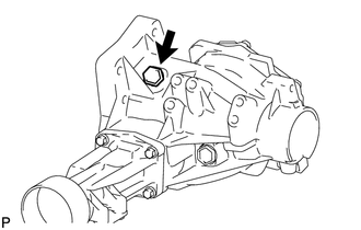
(b) Remove the gasket from the No. 2 transfer case plug.
3. REMOVE NO. 1 TRANSFER CASE PLUG
|
(a) Remove the No. 1 transfer case plug. |
|
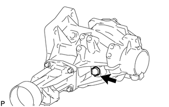
(b) Remove the gasket from the No. 1 transfer case plug.
4. REMOVE TRANSFER DRAIN PLUG
|
(a) Remove the transfer drain plug. |
|
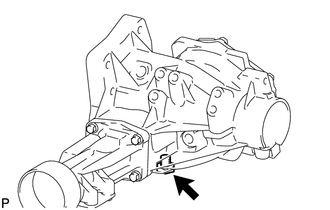
(b) Remove the gasket from the transfer drain plug.
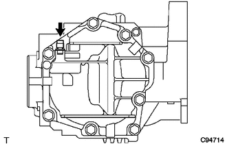
5. REMOVE TRANSFER CASE BREATHER PLUG
|
(a) Using a screwdriver, remove the transfer case breather plug. |
|
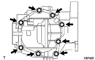
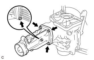
6. REMOVE NO. 1 TRANSFER CASE COVER
|
(a) Remove the 8 bolts. |
|
|
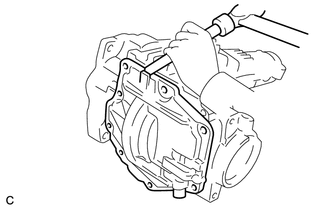
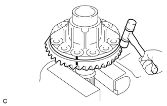
(b) Using a brass bar and a hammer, remove the No. 1 transfer case cover from the transfer case. NOTICE: Place the brass bar on the rib protruding from the case. |
|
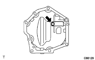
7. REMOVE BREATHER OIL DEFLECTOR
|
(a) Remove the bolt and breather oil deflector. |
|
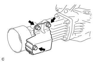
8. REMOVE TRANSFER DYNAMIC DAMPER (for 1AR-FE)
|
(a) Remove the 3 bolts and transfer dynamic damper from the transfer extension housing sub-assembly. |
|
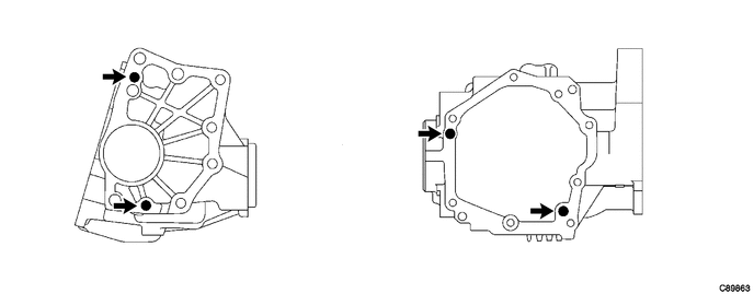
9. REMOVE TRANSFER CASE STRAIGHT PIN
(a) Remove the 4 transfer case straight pins from the transfer case.
10. SECURE TRANSFER ASSEMBLY
(a) Attach the transfer assembly to an overhaul attachment.
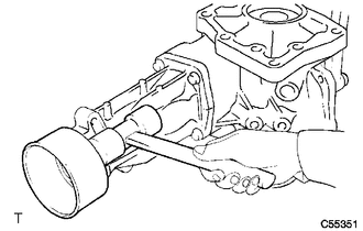
11. REMOVE TRANSFER EXTENSION HOUSING DUST DEFLECTOR
|
(a) Using a plastic hammer, remove the transfer extension housing dust deflector from the transfer extension housing sub-assembly. |
|
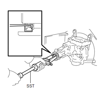
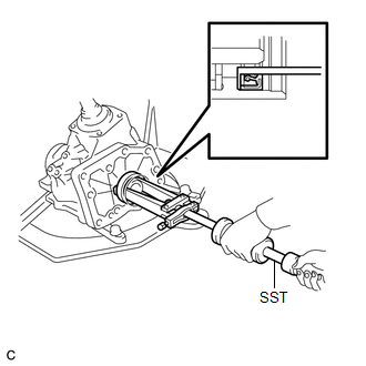
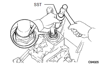
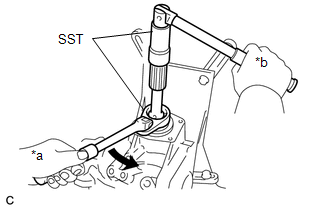
12. REMOVE TRANSFER CASE REAR OIL SEAL
|
(a) Using SST, remove the transfer case rear oil seal from the transfer extension housing sub-assembly. SST: 09308-00010 NOTICE: Be careful not to damage the oil seal contact surface or the inside surface of the oil seal. |
|
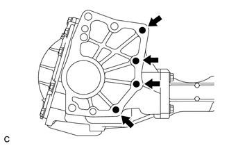
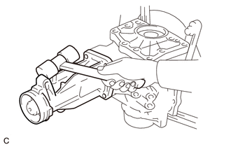
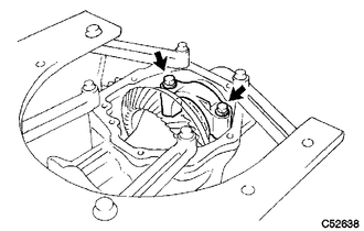
13. REMOVE TRANSFER EXTENSION HOUSING SUB-ASSEMBLY
|
(a) Remove the 4 bolts. |
|
|
(b) Using a plastic hammer, remove the transfer extension housing sub-assembly from the transfer case. |
|
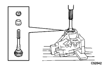
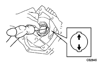
14. INSPECT PRELOAD
.gif)
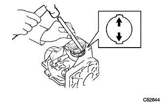
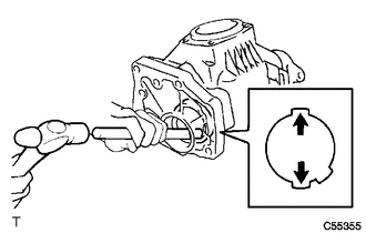
15. INSPECT RING GEAR BACKLASH
16. INSPECT TOOTH CONTACT BETWEEN RING GEAR AND DRIVE PINION
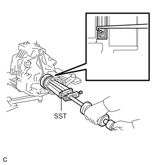
17. REMOVE TRANSFER CASE FRONT OIL SEAL
|
(a) Using SST, remove the transfer case front oil seal from the transfer case. SST: 09308-00010 NOTICE: Do not damage the oil seal contact surface on the case. |
|
18. REMOVE TRANSFER CASE FRONT OIL SEAL (for RH Side)
|
(a) Using SST, remove the transfer case front oil seal from the transfer case. SST: 09308-00010 NOTICE: Do not damage the oil seal contact surface on the case. |
|
19. REMOVE BEARING CAP
|
(a) Remove the 2 bolts and bearing cap. |
|
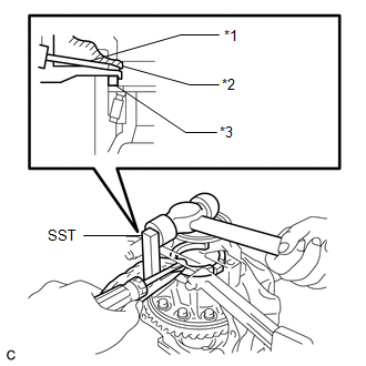
20. REMOVE NO. 1 TRANSFER OUTPUT SHAFT SPACER
|
(a) Using SST, a screwdriver and a hammer, remove the No. 1 transfer output shaft spacer. SST: 09504-22011 Text in Illustration
NOTICE: Do not damage the transfer case. |
|
21. REMOVE NO. 2 TRANSFER RING GEAR MOUNTING CASE WASHER
22. REMOVE TRANSFER RING GEAR MOUNTING CASE
|
(a) Remove the transfer ring gear mounting case from the transfer case. |
|
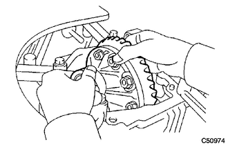
23. REMOVE DRIVEN PINION
|
(a) Using SST and a hammer, unstake the gear nut. SST: 09930-00010 HINT:
|
|
|
(b) Using SST, remove the gear nut. SST: 09326-20011 SST: 09556-16030 Text in Illustration
|
|
|
(c) Using a press, press out the driven pinion, transfer driven pinion rear bearing (inner race) and transfer pinion bearing spacer. NOTICE:
|
|
24. REMOVE TRANSFER DRIVEN PINION FRONT BEARING
|
(a) Using SST and a press, press out the front transfer driven pinion bearing (inner race). SST: 09950-00020 |
|
|
(b) Using a brass bar and a hammer, tap the 2 positions shown in the illustration on the driven pinion front bearing (outer race) to remove it from the case. |
|
25. REMOVE TRANSFER OUTPUT SHAFT WASHER
26. REMOVE RING GEAR MOUNTING CASE BEARING
(a) Remove the ring gear mounting case bearing (outer race) from the transfer ring gear mounting case.
|
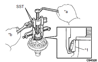
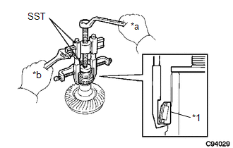
(b) Using SST, remove the ring gear mounting case bearing (inner race) from the transfer ring gear mounting case. SST: 09950-40011 09951-04010 09952-04010 09953-04020 09954-04010 09955-04061 09957-04010 09958-04011 SST: 09950-60010 09951-00440 Text in Illustration
NOTICE: Use SST (09953-04020) after applying grease to its threads and tip. |
|
|
(c) Using SST, remove the ring gear mounting case bearing (inner race) from the transfer ring gear mounting case. SST: 09950-40011 09951-04010 09952-04010 09953-04020 09954-04010 09955-04061 09957-04010 09958-04011 SST: 09950-60010 09951-00400 Text in Illustration
NOTICE: Use SST (09953-04020) after applying grease to its threads and tip. |
|
|
(d) Using a brass bar and a hammer, tap the 2 positions shown in the illustration on the ring gear mounting case bearing (outer race) to remove it from the transfer case. |
|
(e) Remove the ring gear mounting case plate washer.
27. INSPECT RUNOUT OF RING GEAR
28. REMOVE RING GEAR
|
(a) Put matchmarks on the transfer ring gear mounting case and ring gear. Text in Illustration
|
|
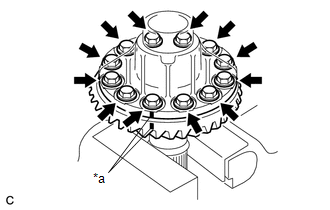
(b) Remove the 12 bolts.
|
(c) Using a plastic hammer, tap on the ring gear to separate it from the transfer ring gear mounting case. NOTICE: Do not damage the ring gear teeth. |
|
29. INSPECT TRANSFER RING GEAR MOUNTING CASE
30. REMOVE TRANSFER DRIVEN PINION REAR BEARING
|
(a) Using a brass bar and a hammer, tap the 2 positions shown in the illustration on the transfer driven pinion rear bearing (outer race) to remove it from the transfer case. |
|
 Removal
REMOVAL
PROCEDURE
1. REMOVE ENGINE ASSEMBLY WITH TRANSAXLE
See page for 2GR-FE
See page for 1AR-FE
2. REMOVE FRONT NO. 1 STABILIZER BRACKET LH
3. REMOVE FRONT NO. 1 STABILIZER BRACKET RH
H ...
 Inspection
INSPECTION
PROCEDURE
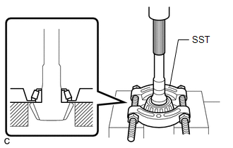
1. INSPECT PRELOAD
(a) Using SST and a torque wrench, measure the preload of the backlash
between the driven pinion and ring gear.
SST: 09326-20011
Preload ...
Other materials about Toyota Venza:
Tire inflation pressure
- Tire inflation pressure
The recommended cold tire inflation pressure and tire size is displayed on the
tire and loading information label.
- Inspection and adjustment procedure
1. Tire valve
2. Tire pressure gauge
Remove the tire val ...
Removal
REMOVAL
PROCEDURE
1. REMOVE REAR DOOR SCUFF PLATE LH
2. REMOVE REAR DOOR OPENING TRIM WEATHERSTRIP LH
3. REMOVE TONNEAU COVER ASSEMBLY (w/ Tonneau Cover)
4. REMOVE DECK BOARD ASSEMBLY
5. REMOVE NO. 3 DECK BOARD SUB-ASSEMBLY
6. REMOVE DECK ...
Calibration
CALIBRATION
1. ROTATION ANGLE SENSOR INITIALIZATION AND TORQUE SENSOR ZERO POINT CALIBRATION
NOTICE:
Clear the rotation angle sensor calibration value, initialize the rotation angle
sensor, and calibrate the torque sensor zero point if any of the followin ...

0.1417