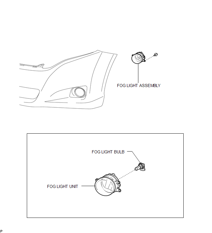
Toyota Venza: Fog Light Assembly
Components
COMPONENTS
ILLUSTRATION
Disassembly
DISASSEMBLY
PROCEDURE
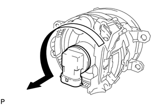
1. REMOVE FOG LIGHT BULB
|
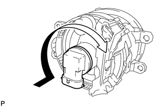
(a) Turn the fog light bulb in the direction indicated by the arrow shown in the illustration and remove it. NOTICE: Do not touch the bulb glass. |
|
Removal
REMOVAL
PROCEDURE
1. REMOVE FRONT BUMPER ASSEMBLY
(See page .gif) )
)
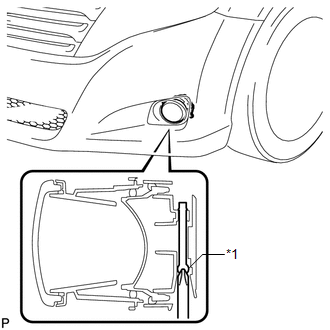
2. REMOVE FOG LIGHT ASSEMBLY
|
(a) Remove the screw. |
|
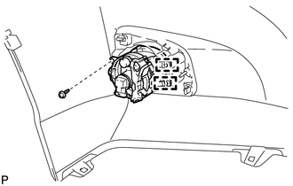
(b) Disengage the 2 guides and remove the fog light assembly.
Adjustment
ADJUSTMENT
CAUTION / NOTICE / HINT
HINT:
It is possible that a bulb is incorrectly installed, affecting fog light aim. Bulb installation should be considered prior to performing the adjustment procedure.
PROCEDURE
1. PREPARE VEHICLE FOR FOG LIGHT AIM ADJUSTMENT
(a) Prepare the vehicle:
- Ensure there is no damage or deformation to the body around the fog lights.
- Fill the fuel tank.
- Make sure that the oil is filled to the specified level.
- Make sure that the coolant is filled to the specified level.
- Inflate the tires to the appropriate pressure.
- Unload the trunk and vehicle, ensuring that the spare tire, tools and jack are in their original positions.
- Sit a person of average weight (68 kg, 150 lb) in the driver's seat.
2. PREPARE FOR FOG LIGHT AIMING
|
(a) Prepare the vehicle:
|
|
(b) Prepare a piece of thick white paper (approximately 2 m (6.6 ft.) (height) x 4 m (13.1 ft.) (width)) to use as a screen.
(c) Draw a vertical line down the center of the screen (V line).
(d) Set the screen as shown in the illustration.
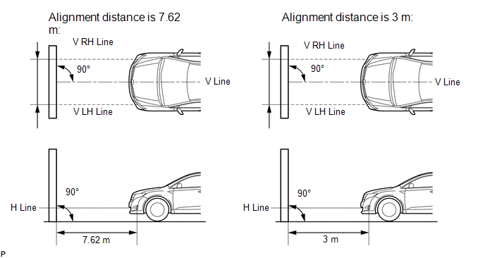
HINT:
- Stand the screen perpendicular to the ground.
- Align the V line on the screen with the center of the vehicle.
|
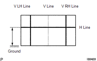
(e) Draw base lines (H, V LH, and V RH lines) on the screen as shown in the illustration. HINT: Mark the fog light bulb center marks on the screen. If the center mark cannot be observed on the fog light, use the center of the fog light bulb or the manufacturer's name marked on the fog light as the center mark. (1) H Line (Fog light height): Draw a horizontal line across the screen so that it passes through the center marks. The H line should be at the same height as the fog light bulb center marks of the fog lights. (2) V LH Line, V RH Line (Center mark position of left-hand (LH) and right-hand (RH) fog lights): Draw two vertical lines so that they intersect the H line at each center mark (aligned with the center of the fog light bulbs). |
|
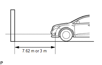
3. INSPECT FOG LIGHT AIMING
(a) Cover the fog light or disconnect the connector of the fog light on the opposite side to prevent light from the fog light that is not being inspected from affecting the fog light aiming inspection.
NOTICE:
Do not keep the fog light covered for more than 3 minutes. The fog light lens is made of synthetic resin, which may melt or be damaged due to excessive heat.
(b) Start the engine.
(c) Turn on the fog lights and check if the upper edge of the hot zone for each fog light matches the upper edge as shown in the illustration.

HINT:
- If the alignment distance is 7.62 m (25 ft.):
The upper edge of the hot zone for the fog light should be 106 mm (4.19 in.) below the H line.
- If the alignment distance is 3 m (9.84 ft.):
The upper edge of the hot zone for the fog light should be 42 mm (1.65 in.) below the H line.
4. ADJUST FOG LIGHT AIMING
|
(a) Adjust the aim vertically: Adjust the aim of each fog light to the specified range by turning each aiming screw with a screwdriver. Text in Illustration
NOTICE: The final turn of the aiming screw should be made in the clockwise direction. If the screw is tightened excessively, loosen it and then retighten it, so that the final turn of the screw is in the clockwise direction. HINT: If it is not possible to correctly adjust fog light aim, check bulb, fog light unit and fog light unit reflector installation. |
|
Reassembly
REASSEMBLY
PROCEDURE
1. INSTALL FOG LIGHT BULB
|
(a) Turn the fog light bulb in the direction indicated by the arrow shown in the illustration to install it. NOTICE: Do not touch the bulb glass. |
|
Installation
INSTALLATION
PROCEDURE
1. INSTALL FOG LIGHT ASSEMBLY
(a) Engage the 2 guides.
(b) Install the fog light assembly with the screw.
2. INSTALL FRONT BUMPER ASSEMBLY
(See page .gif) )
)
 Door Mirror Foot Light
Components
COMPONENTS
ILLUSTRATION
Removal
REMOVAL
CAUTION / NOTICE / HINT
HINT:
Use the same procedure for both the RH and LH sides.
The procedure described below is for the ...

Other materials about Toyota Venza:
Registration
REGISTRATION
PROCEDURE
1. DESCRIPTION OF CODE REGISTRATION
HINT:
The ID codes are the same as recognition codes for the wireless transmitter
and the engine immobiliser function. Registering an ID code enables the
smart key system, the wirel ...
Diagnostic Trouble Code Chart
DIAGNOSTIC TROUBLE CODE CHART
HINT:
If a trouble code is stored during the DTC check, inspect the trouble areas listed
for that code. For details of the code, refer to the "See page" below.
Main Body
DTC Code
Detection Ite ...
Unmatched Key Code (B2795)
DESCRIPTION
This DTC is stored when a key with a key code that has not been registered in
the ECU is inserted into the ignition key cylinder.
DTC No.
DTC Detection Condition
Trouble Area
B2795
Ke ...

0.16