Toyota Venza: Door Control Transmitter(w/o Smart Key System)
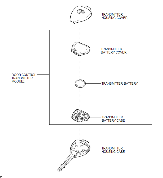
Components
COMPONENTS
ILLUSTRATION
Removal
REMOVAL
PROCEDURE
1. REMOVE TRANSMITTER HOUSING COVER
.gif)
2. REMOVE DOOR CONTROL TRANSMITTER MODULE
Inspection
INSPECTION
PROCEDURE
1. INSPECT DOOR CONTROL TRANSMITTER
(a) Inspect operation of the transmitter.
(1) Remove the battery (lithium battery) from the transmitter (See page
.gif) ).
).
|
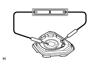
(2) Install a new or non-depleted battery (lithium battery). HINT: When a new or non-depleted battery is not available, first connect 2 new 1.5 batteries in series. Then connect leads to the batteries and apply 3 V to the transmitter, as shown in the illustration. |
|
(3) From outside the vehicle, approximately 1 m (3.28 ft) from the driver side outside door handle, test the transmitter by pointing its key plate at the vehicle and pressing a transmitter switch.
OK:
The door lock can be operated via the transmitter.
The LED comes on more than once.
- The operational area differs depending on the user, the way the transmitter is held and the location.
- The transmitter's faint electric waves may be affected if the area has strong electric waves or noise. The transmitter's operation area may be shortened or the transmitter may not function.
(b) Inspect the battery capacity.
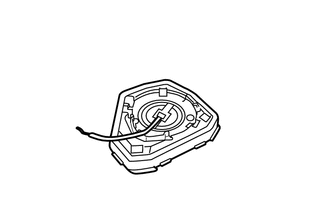
(1) Remove the battery from the electrical key transmitter that does not operate.
Attach a lead wire (0.6 mm (0.0236 in.) in diameter or less including wire sheath)
with tape or equivalent to the negative terminal (See page
).
NOTICE:
Do not wrap the lead wire around a terminal, wedge it between the terminals, or solder it. A terminal may be deformed or damaged, and the battery will not be able to be installed correctly.
|
(2) Carefully pull the lead wire out from the position shown in the illustration and install the previously removed transmitter battery. |
|
(3) Using an oscilloscope, check the transmitter battery voltage waveform.

HINT:
Measure the transmitter battery voltage while pressing the LOCK or UNLOCK switch on the transmitter.
Standard voltage:
|
Item |
Content |
|---|---|
|
Tester Connection |
Battery positive (+) - Battery negative (-) |
|
Tool Setting |
0.5 V/DIV., 100 ms/DIV. |
|
Condition |
Ignition switch off, all doors closed and LOCK or UNLOCK switch is pressed |
|
Specified Condition |
2.2 to 3.2 V (Refer to the waveform) |
If the result is not as specified, replace the transmitter battery.
Installation
INSTALLATION
PROCEDURE
1. INSTALL DOOR CONTROL TRANSMITTER MODULE
.gif)
2. INSTALL TRANSMITTER HOUSING COVER
 Door Control Transmitter(w/ Smart Key System)
Components
COMPONENTS
ILLUSTRATION
Removal
REMOVAL
PROCEDURE
1. REMOVE TRANSMITTER BATTERY
Inspection
INSPECTION
PROCEDURE
1. INSPECT DOOR CONTROL TRANSMITTER
(a) Inspect operati ...
 Front Door Lock
...
Other materials about Toyota Venza:
System Description
SYSTEM DESCRIPTION
1. TOUCH SWITCH OUTLINE
(a) Touch switches are touch-sensitive (interactive) switches operated by touching
the screen. When a switch is pressed, the outer film bends in to contact the inner
glass at the pressed position. By doing this, ...
How To Proceed With Troubleshooting
CAUTION / NOTICE / HINT
HINT:
Use the following procedure to troubleshoot the front power seat control
system (w/ Memory).
*: Use the Techstream.
PROCEDURE
1.
VEHICLE BROUGHT TO WORKSHOP
...
Reassembly
REASSEMBLY
PROCEDURE
1. INSTALL FRONT BLOWER MOTOR SUB-ASSEMBLY
(a) Install the front blower motor sub-assembly with the 3 screws.
2. INSTALL AIR INLET SERVO MOTOR SUB-ASSEMBLY
(a) Insta ...

0.1521