Toyota Venza: Components
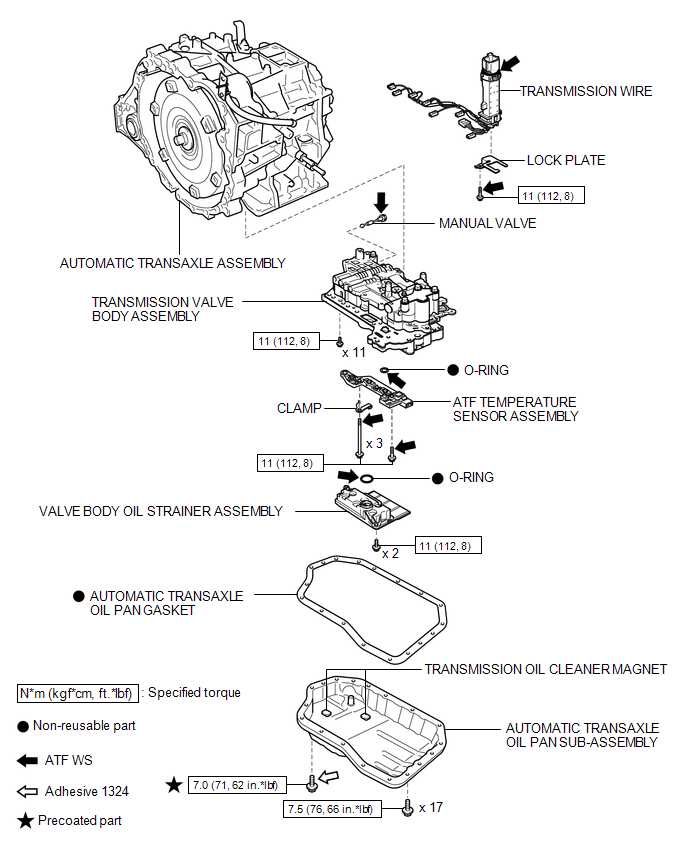
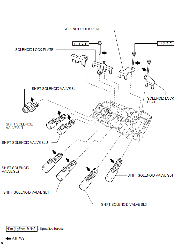
COMPONENTS
ILLUSTRATION
ILLUSTRATION

 Disassembly
DISASSEMBLY
PROCEDURE
1. REMOVE TRANSMISSION WIRE
2. REMOVE ATF TEMPERATURE SENSOR ASSEMBLY
(a) Remove the 4 bolts, ATF temperature sensor assembly and clamp from
the valve body ...
Other materials about Toyota Venza:
Transfer System
Precaution
PRECAUTION
Prior to starting any work, clean the transfer assembly to prevent sand
or mud deposits from entering the assembly.
When removing any light alloy components such as the transfer cover,
do not pry on the component wi ...
Check Mode Procedure
CHECK MODE PROCEDURE
HINT:
Techstream only:
Compared to normal mode, check mode is more sensitive to malfunctions. Therefore,
check mode can detect malfunctions that cannot be detected in normal mode.
NOTICE:
All the stored DTCs and freeze frame data ar ...
Installation
INSTALLATION
PROCEDURE
1. INSTALL REAR SEAT ASSEMBLY LH
(a) Place the rear seat assembly LH in the cabin.
NOTICE:
Be careful not to damage the vehicle body.
(b) Temporarily install the 2 bolts on the front side of the seat.
...

0.1195