Toyota Venza: Removal
REMOVAL
PROCEDURE
1. REMOVE ENGINE ASSEMBLY WITH TRANSAXLE
See page .gif) for 2GR-FE
for 2GR-FE
See page for 1AR-FE
2. REMOVE FRONT NO. 1 STABILIZER BRACKET LH
3. REMOVE FRONT NO. 1 STABILIZER BRACKET RH
HINT:
Perform the same procedure as for the LH side.
4. REMOVE FRONT STABILIZER BAR WITH FRONT STABILIZER LINK ASSEMBLY
5. REMOVE STEERING LINK ASSEMBLY
6. REMOVE FRONT FRAME ASSEMBLY (for 2GR-FE)
7. SEPARATE REAR ENGINE MOUNTING INSULATOR ASSEMBLY (for 1AR-FE)
8. REMOVE FRONT FRAME ASSEMBLY (for 1AR-FE)
9. REMOVE STARTER ASSEMBLY (for 2GR-FE)
10. REMOVE STARTER ASSEMBLY (for 1AR-FE)
11. REMOVE MANIFOLD STAY (for 2GR-FE)
12. REMOVE TRANSFER STIFFENER PLATE RH (for 2GR-FE)
13. REMOVE TRANSFER STIFFENER PLATE RH (for 1AR-FE)
14. SEPARATE WIRE HARNESS (for 2GR-FE)
15. SEPARATE WIRE HARNESS (for 1AR-FE)
16. REMOVE FLEXIBLE HOSE BRACKET SUB-ASSEMBLY (for 2GR-FE)
17. REMOVE AUTOMATIC TRANSAXLE ASSEMBLY (for 2GR-FE)
18. REMOVE AUTOMATIC TRANSAXLE ASSEMBLY (for 1AR-FE)
19. REMOVE TRANSFER ASSEMBLY
|
(a) Remove the 2 bolts and 6 nuts. |
|
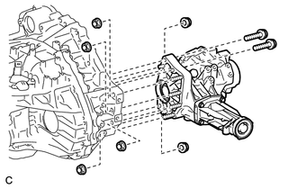
(b) Using a plastic hammer, remove the transfer assembly from the transaxle assembly.
NOTICE:
- Remove the transfer assembly from the transaxle assembly without tilting it.
- During removal, do not hold the transfer assembly by the oil seals on either side of the assembly.
 Components
COMPONENTS
ILLUSTRATION
ILLUSTRATION
ILLUSTRATION
ILLUSTRATION
ILLUSTRATION
ILLUSTRATION
...
 Disassembly
DISASSEMBLY
PROCEDURE
1. REMOVE TRANSFER AND TRANSAXLE SETTING STUD BOLT
(a) Remove the 4 transfer and transaxle setting stud bolts.
2. RE ...
Other materials about Toyota Venza:
Blind Spot Mirrors
The Blind Spot Mirrors increase the view of surrounding area to assist the driver
when checking surrounding area before changing lanes.
1. Blind Spot Mirror field of view
2. Main mirror field of view
- Mirror angle can be adjusted when
►V ...
Removal
REMOVAL
CAUTION / NOTICE / HINT
HINT:
Use the same procedure for the LH side and RH side.
The following procedure is for the LH side.
PROCEDURE
1. REMOVE ENGINE ASSEMBLY WITH TRANSAXLE (for 2GR-FE)
HINT:
Refer to the procedure up to Re ...
Power Back Door cannot be Opened or Closed Using the Power Back Door Switch
DESCRIPTION
When the power back door cannot be opened or closed using the power back door
control switch, one of the following may be malfunctioning: 1) power back door control
switch circuit, 2) power back door ECU (power back door motor unit) or 3) main ...

0.1486