Toyota Venza: Removal
REMOVAL
PROCEDURE
1. DISCONNECT CABLE FROM NEGATIVE BATTERY TERMINAL
NOTICE:
When disconnecting the cable, some systems need to be initialized after the cable
is reconnected (See page .gif) ).
).
2. RECOVER REFRIGERANT FROM REFRIGERATION SYSTEM
3. REMOVE COOL AIR INTAKE DUCT SEAL
4. REMOVE RADIATOR GRILLE
5. REMOVE INLET NO. 2 AIR CLEANER
6. REMOVE AIR CLEANER CAP WITH HOSE
7. REMOVE AIR CLEANER CASE
8. REMOVE BATTERY
9. REMOVE INLET NO. 1 AIR CLEANER
10. REMOVE LOW PITCHED HORN ASSEMBLY
11. REMOVE HIGH PITCHED HORN ASSEMBLY
12. REMOVE HOOD LOCK ASSEMBLY (w/o Engine Hood Courtesy Switch)
13. REMOVE HOOD LOCK ASSEMBLY (w/ Engine Hood Courtesy Switch)
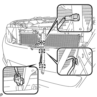
14. REMOVE HOOD LOCK SUPPORT SUB-ASSEMBLY
|
(a) Disengage each clamp. |
|
|
(b) Remove the 2 bolts and hood lock support support sub-assembly. |
|
15. REMOVE UPPER RADIATOR SUPPORT
16. DISCONNECT COOLER REFRIGERANT DISCHARGE HOSE
|
(a) Remove the bolt and disconnect the cooler refrigerant discharge hose from the condenser. |
|
(b) Remove the O-ring from the cooler refrigerant discharge hose.
NOTICE:
Seal the openings of the disconnected parts using vinyl tape to prevent entry of moisture and foreign matter.
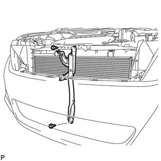
17. DISCONNECT AIR CONDITIONING TUBE AND ACCESSORY ASSEMBLY
|
(a) Remove the bolt and disconnect the air conditioning tube and accessory assembly. |
|
(b) Remove the O-ring from the air conditioning tube and accessory assembly.
NOTICE:
Seal the openings of the disconnected parts using vinyl tape to prevent entry of moisture and foreign matter.
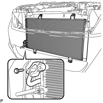
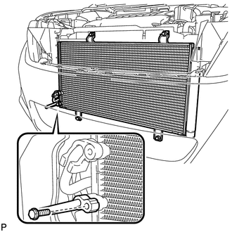
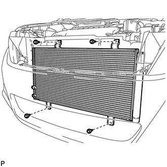
18. REMOVE COOLER CONDENSER ASSEMBLY
|
(a) Remove the 4 bolts and cooler condenser assembly as shown in the illustration. |
|
 On-vehicle Inspection
ON-VEHICLE INSPECTION
PROCEDURE
1. INSPECT COOLER CONDENSER ASSEMBLY
(a) If the cooler condenser assembly fins are dirty, clean them with water and
dry with compressed air.
NOTICE:
Do not damag ...
 Disassembly
DISASSEMBLY
PROCEDURE
1. REMOVE COOLER DRYER
(a) Using a 14 mm straight hexagon wrench, remove the cap from the modulator.
Text in Illustration
*1
...
Other materials about Toyota Venza:
Knock Sensor
Components
COMPONENTS
ILLUSTRATION
Removal
REMOVAL
PROCEDURE
1. REMOVE INTAKE MANIFOLD
(a) Remove the intake manifold (See page ).
2. REMOVE KNOCK SENSOR
(a) Disconnect the sensor connector.
...
Inside Vehicle
General Maintenance
GENERAL MAINTENANCE
CAUTION / NOTICE / HINT
These are maintenance and inspection items that are considered to be
the owner's responsibility.
The owner can do them or they can have them done at a service center.
The ...
Short in Passenger Side Airbag Variable Vent Hole Squib Circuit (B181A/7A-B181D/7A)
DESCRIPTION
The passenger side airbag variable vent hole squib circuit consists of the center
airbag sensor assembly and front passenger airbag assembly.
The center airbag sensor assembly uses this circuit to deploy the airbag when
deployment conditions ...

0.1391