Toyota Venza: Short in Torque Converter Clutch Solenoid Circuit (Shift Solenoid Valve SL) (P2769,P2770)
DESCRIPTION
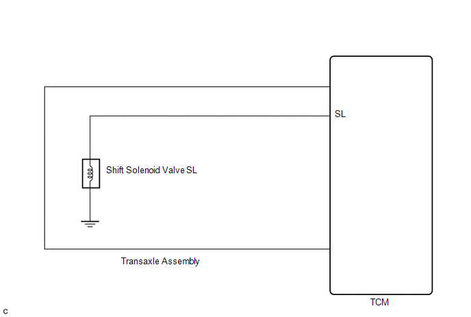
Shift solenoid valve SL is turned on and off by signals from the TCM to control the hydraulic pressure acting on the lock-up relay valve, which then controls operation of the lock-up clutch.
|
DTC No. |
DTC Detection Condition |
Trouble Area |
|---|---|---|
|
P2769 |
TCM detects a short in the shift solenoid valve SL circuit when the shift solenoid valve SL is operated (2 trip detection logic). |
|
|
P2770 |
TCM detects an open in the shift solenoid valve SL circuit when the shift solenoid valve SL is not operated (2 trip detection logic). |
|
Fail-safe function:
If the TCM detects a malfunction, it turns shift solenoid valve SL off.
MONITOR DESCRIPTION
Based on the signals from the throttle position sensor, the air flow meter and the crankshaft position sensor, the TCM sends a signal to shift solenoid valve SL to regulate the hydraulic pressure and provide smoother torque converter engagement. Shift solenoid valve SL responds to commands from the TCM. The valve controls the lock-up relay valve to perform the torque-converter lock-up function. If the TCM detects an open or short circuit for shift solenoid valve SL, it will illuminate the MIL.
MONITOR STRATEGY
|
Related DTCs |
P2769: Shift solenoid valve SL/Range check (Low resistance) P2770: Shift solenoid valve SL/Range check (High resistance) |
|
Required sensors/Components |
Shift solenoid valve SL |
|
Frequency of operation |
Continuous |
|
Duration |
1 time |
|
MIL operation |
2 driving cycles |
|
Sequence of operation |
None |
TYPICAL ENABLING CONDITIONS
P2769: Range check (Low resistance):|
The monitor will run whenever the following DTCs are not present |
None |
|
Command to solenoid |
ON |
|
Time after command to solenoid OFF to ON |
More than 0.008 sec. |
|
The monitor will run whenever the following DTCs are not present |
None |
|
Command to solenoid |
OFF |
|
Time after command to solenoid ON to OFF |
More than 0.008 sec. |
TYPICAL MALFUNCTION THRESHOLDS
P2769: Range check (Low resistance):|
Intelligent power MOS diagnosis fail signals detected while the solenoid is operated |
Fail at solenoid resistance: 8 Ω or less |
|
Intelligent power MOS diagnosis fail signals detected while the solenoid is not operated |
Fail at solenoid resistance: 100 kΩ or more |
COMPONENT OPERATING RANGE
|
Shift solenoid valve SL |
Resistance: 11 to 15 Ω at 20°C (68°F) |
WIRING DIAGRAM
CAUTION / NOTICE / HINT
NOTICE:
Perform the universal trip to clear permanent DTCs (See page
.gif) ).
).
PROCEDURE
|
1. |
INSPECT TRANSMISSION WIRE (SHIFT SOLENOID VALVE SL) |
|
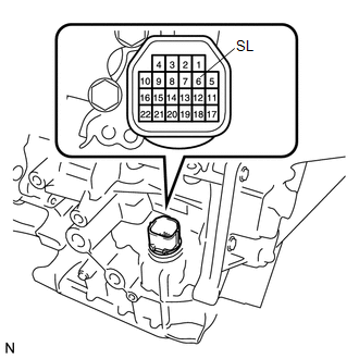
(a) Remove the TCM from the transaxle. |
|
(b) Measure the resistance according to the value(s) in the table below.
Standard Resistance:
|
Tester Connection |
Condition |
Specified Condition |
|---|---|---|
|
6 (SL) - Body ground |
20°C (68°F) |
11 to 15 Ω |
| OK | .gif) |
REPLACE TCM |
|
.gif)
|
2. |
INSPECT SHIFT SOLENOID VALVE SL |
|
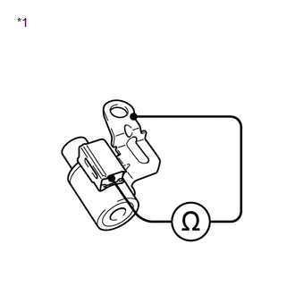
(a) Remove shift solenoid valve SL. |
|
(b) Measure the resistance according to the value(s) in the table below.
Standard Resistance:
|
Tester Connection |
Condition |
Specified Condition |
|---|---|---|
|
Solenoid Connector (SL) - Solenoid Body (SL) |
20°C (68°F) |
11 to 15 Ω |
|
*1 |
Shift Solenoid Valve SL |
| OK | |
REPLACE TRANSMISSION WIRE |
| NG | |
REPLACE SHIFT SOLENOID VALVE SL |
 Diagnostic Trouble Code Chart
DIAGNOSTIC TROUBLE CODE CHART
HINT:
If a DTC is displayed during the DTC check, check the parts listed in
the table below and proceed to the "See page" given.
If multiple s ...
 Pressure Control Solenoid "G" Performance (Shift Solenoid Valve SL4) (P2808)
DESCRIPTION
The TCM uses the vehicle speed signal and signals from the transmission speed
sensors (NC, NT) to detect the actual gear (1st, 2nd, 3rd, 4th, 5th or 6th gear).
Then the TCM compares th ...
Other materials about Toyota Venza:
Removal
REMOVAL
PROCEDURE
1. REMOVE ENGINE ASSEMBLY WITH TRANSAXLE
See page for 2GR-FE
See page for 1AR-FE
2. REMOVE FRONT NO. 1 STABILIZER BRACKET LH
3. REMOVE FRONT NO. 1 STABILIZER BRACKET RH
HINT:
Perform the same procedure as for the LH side.
4. REM ...
Compass
The compass on the inside rear view mirror indicates the direction in which
the vehicle is heading.
- Operation
To turn the compass on or off, push and hold “AUTO” for longer than 3 seconds.
- Displays and directions
Calibrating the c ...
Transfer Case Front Oil Seal(when Using The Engine Support Bridge)
Components
COMPONENTS
ILLUSTRATION
Replacement
REPLACEMENT
PROCEDURE
1. REMOVE TRANSFER ASSEMBLY
See page
2. REMOVE TRANSFER CASE FRONT OIL SEAL
(a) Using SST, remove the transfer case front oil seal from the transfer
case.
S ...

0.1341