Toyota Venza: Disassembly
DISASSEMBLY
PROCEDURE
1. REMOVE INTAKE VALVE
|
(a) Using SST and wooden blocks, compress the compression spring and remove the valve spring retainer locks. SST: 09202-70020 09202-00010 |
|
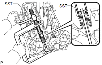
(b) Remove the retainer, compression spring and valve.
HINT:
Arrange the removed parts in the correct order.
2. REMOVE EXHAUST VALVE
|
(a) Using SST and wooden blocks, compress the compression spring and remove the valve spring retainer locks. SST: 09202-70020 09202-00010 |
|
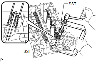
(b) Remove the retainer, compression spring and valve.
HINT:
Arrange the removed parts in the correct order.
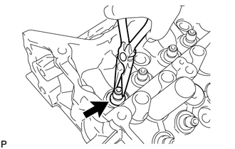
3. REMOVE VALVE STEM OIL SEAL
|
(a) Using needle-nose pliers, remove the oil seals. |
|
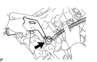
4. REMOVE VALVE SPRING SEAT
|
(a) Using compressed air and a Magnet Hand, remove the valve spring seat by blowing air onto it. |
|
5. REMOVE NO. 1 STRAIGHT SCREW PLUG
NOTICE:
If water leaks from the No. 1 screw plug or the plug is corroded, replace it.
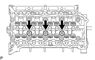
(a) Using a 10 mm hexagon wrench, remove the 3 screw plugs and 3 gaskets.
6. REMOVE NO. 2 STRAIGHT SCREW PLUG
NOTICE:
If water leaks from the No. 2 screw plug or the plug is corroded, replace it.
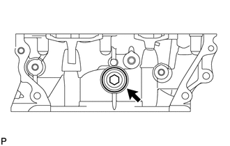
(a) Using a 14 mm hexagon wrench, remove the screw plug and gasket.
7. REMOVE STUD BOLT
NOTICE:
If a stud bolt is deformed or its threads are damaged, replace it.
 Components
COMPONENTS
ILLUSTRATION
...
 Inspection
INSPECTION
PROCEDURE
1. INSPECT CYLINDER HEAD SUB-ASSEMBLY
(a) Using a precision straightedge and feeler gauge, measure the warpage of the
contact surfaces where the cylinder head contacts the cy ...
Other materials about Toyota Venza:
Horn
Components
COMPONENTS
ILLUSTRATION
Inspection
INSPECTION
PROCEDURE
1. INSPECT LOW PITCHED HORN ASSEMBLY
(a) Apply battery voltage and check the operation of the low pitched
horn assembly according to the table below.
OK:
...
Open in Front Floor Electrical Key Oscillator Circuit (B27A5)
DESCRIPTION
The certification ECU (smart key ECU assembly) generates a request signal and
sends it to the indoor electrical key oscillator (for front floor). To detect the
key inside the cabin, the indoor electrical key oscillator (for front floor) create ...
Front Passenger Side Seat Belt Warning Light Malfunction
DESCRIPTION
The occupant classification ECU detects the state of the front seat inner belt
assembly RH and load sensor when the front passenger side seat is occupied with
the ignition switch ON. If the front passenger side seat belt is not fastened, the
...

0.1257