Toyota Venza: Disassembly
DISASSEMBLY
PROCEDURE
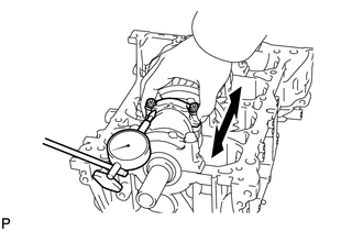
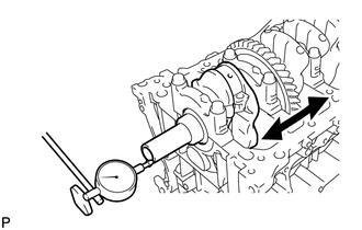
1. INSPECT CONNECTING ROD THRUST CLEARANCE
|
(a) Using a dial indicator, measure the thrust clearance while moving the connecting rod back and forth. Standard thrust clearance: 0.160 to 0.512 mm (0.00630 to 0.0202 in.) Maximum thrust clearance: 0.512 mm (0.0202 in.) If the thrust clearance is more than the maximum, replace the connecting rod. If necessary, replace the crankshaft. |
|
2. INSPECT CONNECTING ROD OIL CLEARANCE
|
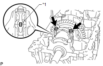
(a) Check the alignment marks on the connecting rod and cap to ensure correct reassembly. Text in Illustration
|
|
|
(b) Remove the 2 bolts and connecting rod cap. HINT: Keep the lower bearing and connecting rod cap together. |
|
(c) Clean the crank pin and bearing.
(d) Check the crank pin and bearing for pitting and scratches.
If the crank pin or bearing is damaged, replace the bearings. If necessary, replace the crankshaft.
|
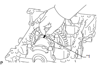
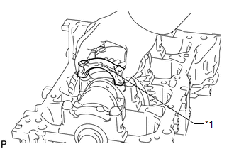
(e) Lay a strip of Plastigage on the crank pin. Text in Illustration
|
|
|
(f) Check that the front mark of the connecting rod cap is facing in the correct direction. Text in Illustration
|
|
|
(g) Apply a light coat of engine oil to the threads and under the heads of the connecting rod bolts. |
|
(h) Install and alternately tighten the bolts of the connecting rod cap in several steps.
Torque:
40 N·m {408 kgf·cm, 30 ft·lbf}
NOTICE:
Do not turn the crankshaft during the measurement.
If any one of the connecting rod bolts does not meet the torque specification, replace the connecting rod bolts.
|
(i) Mark the front of each connecting rod bolt with paint. |
|
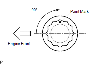
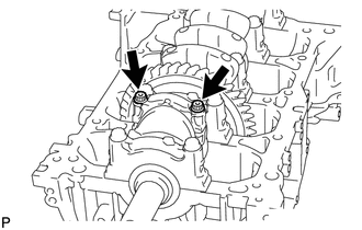
(j) Tighten the bolts 90° as shown in the illustration.
NOTICE:
Do not turn the crankshaft during the measurement.
(k) Remove the 2 bolts and connecting rod cap.
HINT:
Keep the lower bearing and connecting rod cap together.
|
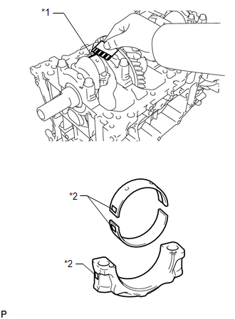
(l) Measure the Plastigage at its widest point. Text in Illustration
Standard oil clearance: 0.030 to 0.063 mm (0.00118 to 0.00248 in.) Maximum oil clearance: 0.07 mm (0.00276 in.) NOTICE: Remove the Plastigage completely after the measurement. If the oil clearance is more than the maximum, replace the connecting rod bearing. If necessary, grind or replace the crankshaft. HINT: If replacing a bearing, select a new one with the same number as marked on the connecting rod. There are 3 sizes of standard bearings, marked "1", "2" and "3" accordingly. Standard crank pin diameter: 51.492 to 51.500 mm (2.0272 to 2.0276 in.) Standard Connecting Rod Big End Inside Diameter:
Standard Size Bearing Center Wall Thickness:
|
|
(m) Perform the inspection above for each cylinder.
3. REMOVE PISTON WITH CONNECTING ROD
|
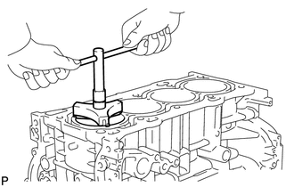
(a) Using a ridge reamer, remove all the carbon from the top of the cylinder. |
|
(b) Remove the 8 bolts, 4 connecting rod caps and 4 lower bearings.
(c) Push the piston, connecting rod assembly and upper bearing through the top of the cylinder block.
HINT:
- Keep the bearings, connecting rod and cap together.
- Arrange the piston and connecting rod assemblies in the correct order.
- Be sure to arrange the removed piston and connecting rod assemblies in such a way that they can be reinstalled exactly as before.
4. REMOVE CONNECTING ROD BEARING
(a) Remove the connecting rod bearings from the connecting rods and connecting rod caps.
HINT:
Arrange the removed parts in the correct order.
5. INSPECT CRANKSHAFT THRUST CLEARANCE
|
(a) Using a dial indicator, measure the thrust clearance while prying the crankshaft back and forth with a screwdriver. Standard thrust clearance: 0.04 to 0.24 mm (0.00157 to 0.00945 in.) Maximum thrust clearance: 0.30 mm (0.0118 in.) If the thrust clearance is more than the maximum, replace the thrust washers as a set. If necessary, replace the crankshaft. Standard thrust washer thickness: 1.93 to 1.98 mm (0.0760 to 0.0780 in.) |
|
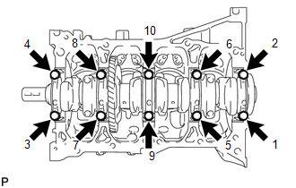
6. REMOVE CRANKSHAFT
|
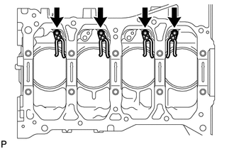
(a) Using several steps, uniformly loosen and remove the 10 bearing cap bolts in the sequence shown in the illustration. |
|
(b) Remove the 5 bearing caps from the cylinder block.
HINT:
- Keep the No. 2 crankshaft bearings and crankshaft bearing caps together.
- Arrange the bearing caps in the correct order.
(c) Remove the crankshaft from the cylinder block.
HINT:
Keep the crankshaft bearings and crankshaft thrust washers together with the cylinder block.
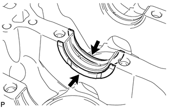
(d) Check each crankshaft journal and bearing for pitting and scratches.
If the journal or bearing is damaged, replace the bearings. If necessary, replace the crankshaft.
7. REMOVE CRANKSHAFT THRUST WASHER
|
(a) Remove the thrust washers from the cylinder block. |
|
8. REMOVE CRANKSHAFT BEARING
(a) Remove the crankshaft bearings from the cylinder block and bearing caps.
HINT:
Arrange the bearings in the correct order.
9. REMOVE CRANKSHAFT PULLEY KEY
(a) Using a screwdriver, remove the 2 pulley keys from the crankshaft.
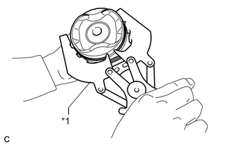
10. REMOVE PISTON RING SET
|
(a) Using a piston ring expander, remove the 2 compression rings. Text in Illustration
|
|
(b) Remove the oil ring and expander by hand.
HINT:
Arrange the removed parts in the correct order.
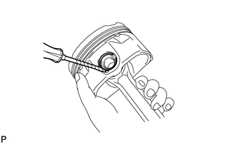
11. REMOVE PISTON PIN HOLE SNAP RING
|
(a) Insert a small screwdriver into the service hole, pry out the snap ring on the front side. NOTICE: Do not remove the snap ring on the rear side unless it is necessary. When the snap ring needs to be removed, be careful not to damage the piston. |
|
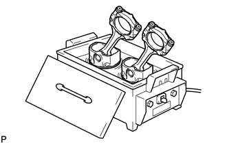
12. REMOVE PISTON
|
(a) Gradually heat the piston up to 80 to 90°C (176 to 194°F). |
|
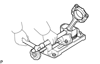
|
(b) Using a plastic-faced hammer and brass bar, lightly tap out the piston pin. Then remove the connecting rod. HINT:
|
|
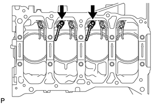
13. REMOVE NO. 1 OIL NOZZLE SUB-ASSEMBLY
|
(a) Using a 5 mm hexagon wrench, remove the 2 bolts and 2 oil nozzles. |
|
14. REMOVE NO. 2 OIL NOZZLE SUB-ASSEMBLY
|
(a) Using a 5 mm hexagon wrench, remove the 4 bolts and 4 oil nozzles. |
|
15. REMOVE STUD BOLT
NOTICE:
If a stud bolt is deformed or its threads are damaged, replace it.
 Components
COMPONENTS
ILLUSTRATION
...
 Inspection
INSPECTION
PROCEDURE
1. INSPECT CYLINDER BLOCK FOR WARPAGE
(a) Using a precision straightedge and feeler gauge, check the surface
that is in contact with the cylinder head gasket for ...
Other materials about Toyota Venza:
Inspection
INSPECTION
PROCEDURE
1. INSPECT ATF TEMPERATURE SENSOR ASSEMBLY
(a) Measure the resistance according to the value(s) in the table below.
Standard Resistance:
Tester Connection
Condition
Sp ...
LVL Terminal Circuit
DESCRIPTION
By connecting terminals LVL and CG of the DLC3, the headlight leveling
ECU assembly initializes the height control sensor signal.
WIRING DIAGRAM
PROCEDURE
1.
CHECK HARNESS AND CONNECTOR (DLC3 - HEADLIGH ...
Power Back Door Main Switch
Components
COMPONENTS
ILLUSTRATION
Inspection
INSPECTION
PROCEDURE
1. INSPECT POWER BACK DOOR MAIN SWITCH
(a) Check that the switch function.
(1) Measure the resistance according to the value(s) in the table below.
Standard Resistance:
...

0.1562