Toyota Venza: Components
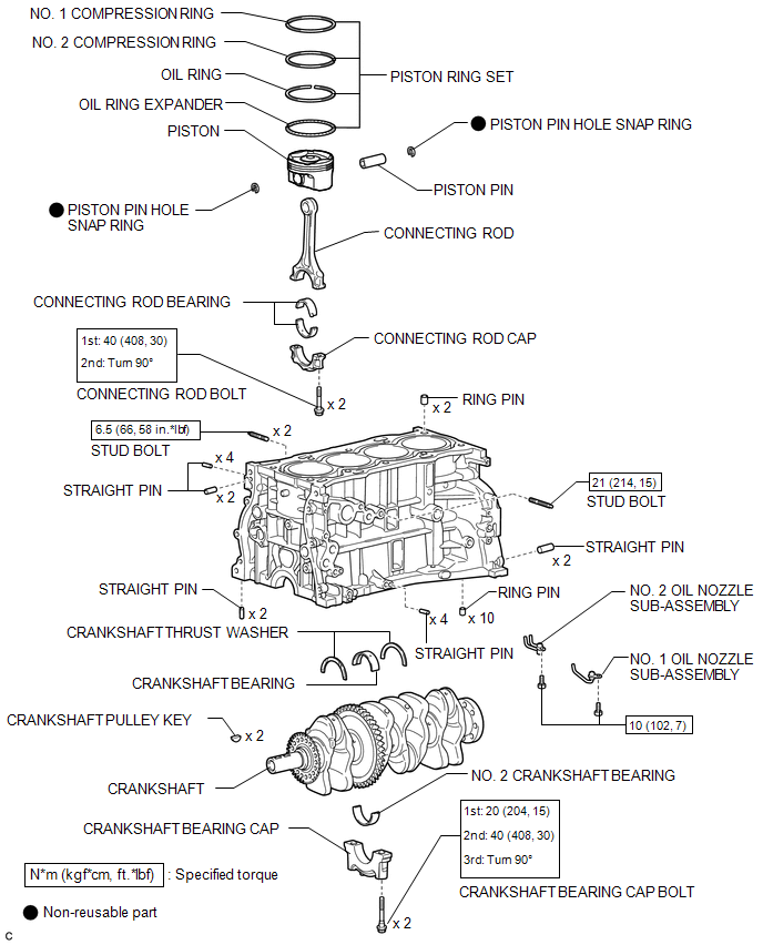
COMPONENTS
ILLUSTRATION
 Precaution
PRECAUTION
HINT:
Any digits beyond the 0.01 mm (1/1000 in.) place for standard, minimum
and maximum values should be used as a reference only.
When both standard and maximum or minim ...
 Disassembly
DISASSEMBLY
PROCEDURE
1. INSPECT CONNECTING ROD THRUST CLEARANCE
(a) Using a dial indicator, measure the thrust clearance while moving
the connecting rod back and forth.
Standard ...
Other materials about Toyota Venza:
Brake fluid
- Checking fluid level
The brake fluid level should be between the “MAX” and “MIN” lines on the tank.
Make sure to check the fluid type and prepare the necessary items.
- Adding fluid
- Brake fluid can absorb moisture from the ...
Driving assist systems
To help enhance driving safety and performance, the following systems operate
automatically in response to various driving situations.
Be aware, however, that these systems are supplementary and should not be relied
upon too heavily when operating the veh ...
Door Courtesy Switch Circuit
DESCRIPTION
When an additional transponder key is registered, the transponder key ECU assembly
detects the front door courtesy light switch assembly (for driver side) open/close
condition, and enters the key registration mode.
WIRING DIAGRAM
CAUTION / ...

0.1712