Toyota Venza: Inspection
INSPECTION
PROCEDURE
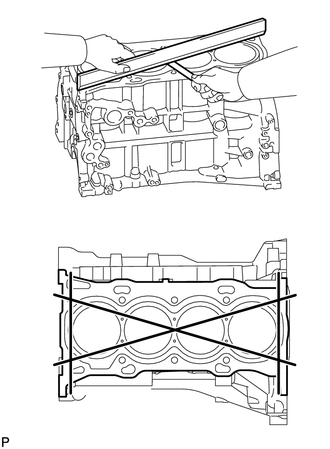
1. INSPECT CYLINDER BLOCK FOR WARPAGE
|
(a) Using a precision straightedge and feeler gauge, check the surface that is in contact with the cylinder head gasket for warpage. Maximum Warpage: 0.05 mm (0.00197 in.) If the warpage is more than the maximum, replace the cylinder block. |
|
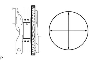
2. INSPECT CYLINDER BORE
(a) Using a cylinder gauge, measure the cylinder bore diameter at positions (A) and (B) in the thrust and axial directions.
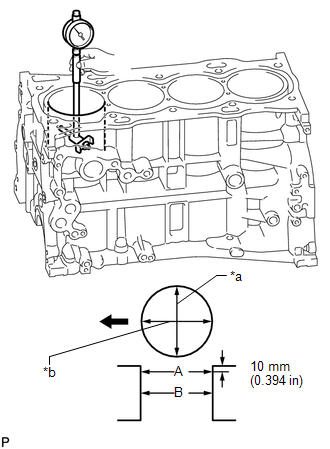
Standard Diameter:
90.000 to 90.013 mm (3.543 to 3.544 in.)
Maximum Diameter:
90.13 mm (3.548 in.)
Text in Illustration|
*a |
Thrust Direction |
|
*b |
Axial Direction |
.png) |
Front |
If the average diameter of the 4 positions is more than the maximum, replace the cylinder block.
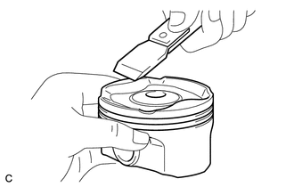
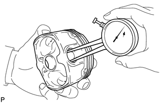
3. INSPECT PISTON
|
(a) Using a gasket scraper, remove the carbon from the piston top. |
|
|
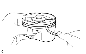
(b) Using a groove cleaning tool or a broken ring, clean the ring grooves. |
|
|
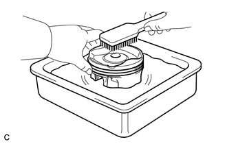
(c) Using a brush and solvent, thoroughly clean the piston. NOTICE: Do not use a wire brush. |
|
|
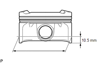
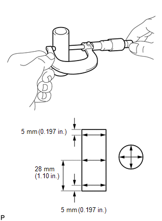
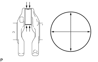
(d) Using a micrometer, measure the piston diameter at a position that is 10.5 mm (0.413 in.) from the bottom of the piston (refer to the illustration). Standard Piston Diameter: 89.980 to 89.990 mm (3.5425 to 3.5429 in.) If the diameter is not as specified, replace the piston. |
|
4. INSPECT PISTON OIL CLEARANCE
(a) Measure the cylinder bore diameter in the thrust direction.
(b) Subtract the piston diameter measurement from the cylinder bore diameter measurement.
Standard Oil Clearance:
0.010 to 0.033 mm (0.000394 to 0.00130 in.)
Maximum Oil Clearance:
0.10 mm (0.00394 in.)
If the piston oil clearance is more than the maximum, replace all the pistons. If necessary, replace the cylinder block.
5. INSPECT RING GROOVE CLEARANCE
|
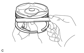
(a) Using a feeler gauge, measure the ring groove clearance between the new piston ring and the wall of the ring groove. Standard Ring Groove Clearance:
If the ring groove clearance is not as specified, replace the piston with pin. |
|
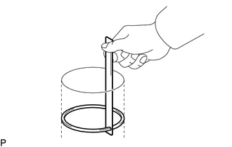
6. INSPECT PISTON RING END GAP
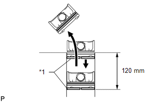
(a) Insert the piston ring into the cylinder bore.
|
(b) Using a piston, push the piston ring a little beyond the bottom of the ring travel, 120 mm (4.72 in.) from the top of the cylinder block. Text in Illustration
|
|
|
(c) Using a feeler gauge, measure the end gap. Standard End Gap:
Maximum End Gap:
If the piston ring end gap is more than the maximum, replace the piston ring. If the piston ring end gap is more than the maximum, even with a new piston ring, replace the cylinder block. |
|
7. INSPECT PISTON PIN OIL CLEARANCE
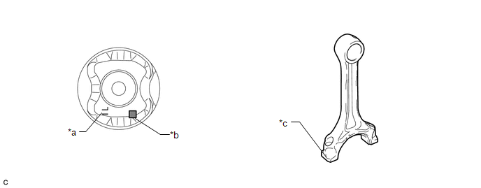
(a) Check each mark on the piston, piston pin and connecting rod sub-assembly.
 Text in Illustration
|
*a |
Front Mark |
*b |
Piston Pin Hole Inside Diameter Mark |
|
*c |
Connecting Rod Sub-assembly Small End Bush Inside Diameter Mark |
- |
- |
HINT:
The front mark is "1L" printed in raised letters.
|
(b) Using a caliper gauge, measure the inside diameter of the piston pin hole. Standard Piston Pin Hole Inside Diameter:
|
|
|
(c) Using a micrometer, measure the piston pin diameter. Standard Piston Pin Diameter:
If the diameter is not as specified, replace the piston pin. |
|
|
(d) Using a caliper gauge, measure the connecting rod sub-assembly small end bush inside diameter. Standard Connecting Rod Sub-assembly Small End Bush Inside Diameter:
If the diameter is not as specified, replace the connecting rod sub-assembly. |
|
(e) Subtract the piston pin diameter measurement from the piston pin hole inside diameter measurement.
Standard Oil Clearance:
0.001 to 0.007 mm (0.0000394 to 0.000276 in.)
Maximum Oil Clearance:
0.013 mm (0.000512 in.)
If the oil clearance is more than the maximum, replace the piston and piston pin as a set.
(f) Subtract the piston pin diameter measurement from the connecting rod sub-assembly small end bush inside diameter measurement.
Standard Oil Clearance:
0.005 to 0.011 mm (0.000197 to 0.000433 in.)
Maximum Oil Clearance:
0.017 mm (0.000669 in.)
If the oil clearance is more than the maximum, replace the connecting rod sub-assembly. If necessary, replace the connecting rod sub-assembly and piston pin as a set.
8. INSPECT CONNECTING ROD SUB-ASSEMBLY
(a) Using a connecting rod sub-assembly aligner and feeler gauge, check the connecting rod sub-assembly alignment.
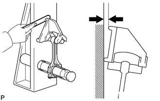
(1) Check for bend.
Maximum Bend:
0.05 mm (0.00197 in.) per 100 mm (3.94 in.)
If the bend is more than the maximum, replace the connecting rod sub-assembly.
|
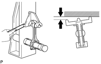
(2) Check for twist. Maximum Twist: 0.15 mm (0.00591 in.) per 100 mm (3.94 in.) If the twist is more than the maximum, replace the connecting rod sub-assembly. |
|
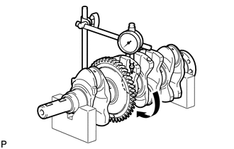
9. INSPECT CRANKSHAFT
|
(a) Inspect for runout. (1) Place the crankshaft on V-blocks. (2) Using a dial indicator, measure the runout as shown in the illustration. Maximum Runout: 0.03 mm (0.00118 in.) If the runout is more than the maximum, replace the crankshaft. |
|
|
(b) Inspect the main journals. (1) Using a micrometer, measure the diameter of each main journal. Standard Main Journal Diameter: 54.988 to 55.000 mm (2.1649 to 2.1654 in.) If the diameter is not as specified, check the crankshaft oil clearance. If necessary, replace the crankshaft. (2) Check each main journal for taper and out-of-round as shown in the illustration. Maximum Taper and Out-of-round: 0.003 mm (0.000118 in.) If the taper or out-of-round is more than the maximum, replace the crankshaft. |
|
|
(c) Inspect the crank pin. (1) Using a micrometer, measure the diameter of each crank pin. Standard Crank Pin Diameter: 51.492 to 51.500 mm (2.027 to 2.028 in.) If the crank pin diameter is not as specified, check the connecting rod sub-assembly oil clearance. If necessary, replace the crankshaft. (2) Check each crank pin for taper and out-of-round. Maximum Taper and Out-of-round: 0.003 mm (0.000118 in.) If the taper or out-of-round is more than the maximum, replace the crankshaft. |
|
10. INSPECT CRANKSHAFT OIL CLEARANCE
(a) Install the crankshaft bearings (See page
.gif) ).
).
(b) Install the crankshaft thrust washers (See page
).
|
(c) Clean each main journal and crankshaft bearing. Text in Illustration
|
|
(d) Place the crankshaft on the cylinder block.
(e) Lay a strip of Plastigage across each crankshaft main journal.
(f) Install the crankshaft bearing caps (See page
).
NOTICE:
Do not turn the crankshaft.
(g) Remove the crankshaft bearing caps (See page
).
(h) Measure the Plastigage at its widest point.
 Text in Illustration
|
*a |
Plastigage |
Standard Oil Clearance:
0.017 to 0.040 mm (0.000669 to 0.00157 in.)
Maximum Oil Clearance:
0.05 mm (0.00197 in.)
NOTICE:
Remove the Plastigage completely after the measurement.
If the crankshaft oil clearance is more than the maximum, replace the crankshaft bearings. If necessary, replace the crankshaft.
HINT:
If replacing a crankshaft bearing, select a new one with the same number. If the number of the crankshaft bearing cannot be determined, calculate the correct crankshaft bearing number by adding together the numbers imprinted on the cylinder block and crankshaft. Then select a new crankshaft bearing with the calculated number. There are 4 sizes of standard bearings, marked "1", "2", "3" or "4" accordingly.
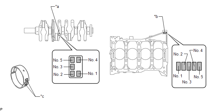 Text in Illustration
|
*a |
Crankshaft Number Mark (B) |
*b |
Cylinder Block Number Mark (A) |
|
*c |
Diameter Mark |
- |
- |
- EXAMPLE
Cylinder block (A) "3" + Crankshaft (B) "4" = Total "7"
Select the bearing marked "3".
Bearing Chart:
(A) + (B)
Use Bearing
0 to 2
1
3 to 5
2
6 to 8
3
9 to 11
4
Standard Cylinder Block Journal Inside Diameter (A):
Item
Specified Condition
Mark 0
59.000 to 59.002 mm (2.32283 to 2.32291 in.)
Mark 1
59.003 to 59.004 mm (2.32295 to 2.32299 in.)
Mark 2
59.005 to 59.006 mm (2.32303 to 2.32307 in.)
Mark 3
59.007 to 59.009 mm (2.32311 to 2.32318 in.)
Mark 4
59.010 to 59.011 mm (2.32322 to 2.32326 in.)
Mark 5
59.012 to 59.013 mm (2.32330 to 2.32334 in.)
Mark 6
59.014 to 59.016 mm (2.32338 to 2.32346 in.)
Standard Crankshaft Main Journal Diameter (B):
Item
Specified Condition
Mark 0
54.999 to 55.000 mm (2.16531 to 2.16535 in.)
Mark 1
54.997 to 54.998 mm (2.16523 to 2.16527 in.)
Mark 2
54.995 to 54.996 mm (2.16515 to 2.16519 in.)
Mark 3
54.993 to 54.994 mm (2.16507 to 2.16511 in.)
Mark 4
54.991 to 54.992 mm (2.16500 to 2.16504 in.)
Mark 5
54.988 to 54.990 mm (2.16488 to 2.16496 in.)
Standard Bearing Center Wall Thickness:
Item
Specified Condition
Mark 1
1.991 to 1.994 mm (0.07839 to 0.07850 in.)
Mark 2
1.995 to 1.997 mm (0.07854 to 0.07862 in.)
Mark 3
1.998 to 2.000 mm (0.07866 to 0.07874 in.)
Mark 4
2.001 to 2.003 mm (0.07878 to 0.07886 in.)
(i) Perform the inspection above for each journal.
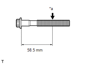
11. INSPECT CRANKSHAFT BEARING CAP BOLT
|
(a) Using a vernier caliper, measure the diameter of the bolt at the point shown in the illustration. Standard Diameter: 9.77 to 9.96 mm (0.385 to 0.392 in.) Minimum Diameter: 9.1 mm (0.358 in.) Measuring Point (Distance from the Seat): 58.5 mm (2.30 in.) Text in Illustration
HINT:
|
|
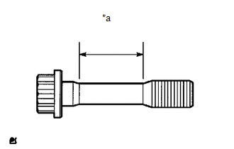
12. INSPECT CONNECTING ROD BOLT
|
(a) Using a vernier caliper, measure the diameter of the connecting rod bolt in the area show in the illustration. Standard Diameter: 8.5 to 8.6 mm (0.335 to 0.339 in.) Minimum Diameter: 8.3 mm (0.327 in.) Text in Illustration
If the diameter is less than the minimum, replace the connecting rod bolt. HINT:
|
|
13. INSPECT NO. 1 OIL NOZZLE SUB-ASSEMBLY
|
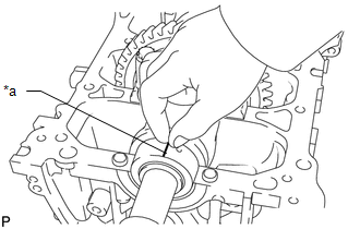
(a) Push the check valve with a pin to check if it is stuck. Text in Illustration
If stuck, replace the No. 1 oil nozzle sub-assembly. |
|
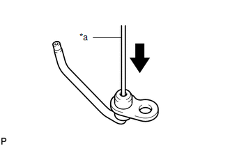
(b) Push the check valve with a pin to check if it moves smoothly.
If it does not move smoothly, clean or replace the No. 1 oil nozzle sub-assembly.
|
(c) Apply air into (A). Check that air does not leak through (B). If air leaks, clean or replace the No. 1 oil nozzle sub-assembly. |
|
|
(d) Push the check valve while applying air into (A). Check that air passes through (B). Text in Illustration
If air does not pass through (B), clean or replace the No. 1 oil nozzle sub-assembly. |
|
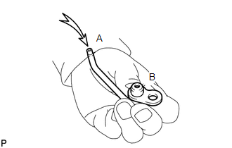
14. INSPECT NO. 2 OIL NOZZLE SUB-ASSEMBLY
|
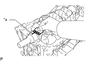
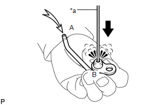
(a) Push the check valve with a pin to check if it is stuck. Text in Illustration
If stuck, replace the No. 2 oil nozzle sub-assembly. |
|
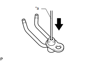
(b) Push the check valve with a pin to check if it moves smoothly.
If it does not move smoothly, clean or replace the No. 2 oil nozzle sub-assembly.
|
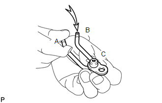
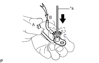
(c) While covering (A), apply air into (B). Check that air does not leak through (C). Perform the check again while covering (B) and applying air into (A). If air leaks, clean or replace the No. 2 oil nozzle sub-assembly. |
|
|
(d) Push the check valve while covering (A), and apply air into (B). Check that air passes through (C). Perform the check again while covering (B), pushing the check valve and applying air into (A). Text in Illustration
If air does not pass through (C), clean or replace the No. 2 oil nozzle sub-assembly. |
|
 Disassembly
DISASSEMBLY
PROCEDURE
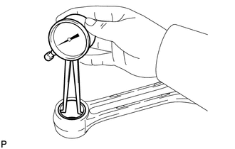
1. INSPECT CONNECTING ROD THRUST CLEARANCE
(a) Using a dial indicator, measure the thrust clearance while moving
the connecting rod back and forth.
Standard ...
 Reassembly
REASSEMBLY
CAUTION / NOTICE / HINT
HINT:
Perform "Inspection After Repair" after replacing the piston or piston ring (See
page ).
PROCEDURE
1. INSTALL STUD BOLT
NOTICE:
If a stud b ...
Other materials about Toyota Venza:
Rear Occupant Classification Sensor LH Collision Detection (B1787)
DESCRIPTION
DTC B1787 is output when the occupant classification ECU receives a collision
detection signal sent by the rear occupant classification sensor LH if an accident
occurs.
DTC B1787 is also output when the front seat assembly RH is subjected to ...
Removal
REMOVAL
CAUTION / NOTICE / HINT
HINT:
Perform "Inspection After Repair" after replacing the fuel injector assembly
(See page ).
PROCEDURE
1. DISCHARGE FUEL SYSTEM PRESSURE
(a) Discharge fuel system pressure (See page
).
2. DISCONNECT CABL ...
Slip Indicator Light does not Come ON
DESCRIPTION
The skid control ECU is connected to the combination meter via CAN communication.
WIRING DIAGRAM
Refer to Slip Indicator Light Remains ON (See page
).
PROCEDURE
1.
CHECK CAN COMMUNICATION SYSTEM
(a) Check if ...

0.1519