Toyota Venza: Driver Side Door ECU Communication Stop (B2321)
DESCRIPTION
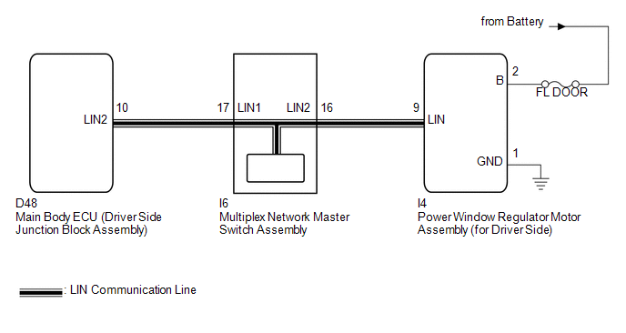
This DTC is stored when LIN communication between the power window regulator motor assembly (for driver side) and main body ECU (driver side junction block assembly) stops for more than 10 seconds.
|
DTC No. |
DTC Detection Condition |
Trouble Area |
|---|---|---|
|
B2321 |
No communication between the power window regulator motor assembly (for driver side) and main body ECU (driver side junction block assembly) for more than 10 seconds. |
|
WIRING DIAGRAM
CAUTION / NOTICE / HINT
NOTICE:
- When the power window regulator motor assembly (for driver side) is
replaced or removed and reinstalled, it requires initialization (See page
.gif) ).
). - When using the Techstream to troubleshoot with the ignition switch off:
Connect the Techstream to the DLC3, and turn the courtesy switch on and off at 1.5-second intervals until communication between the Techstream and vehicle begins.
PROCEDURE
|
1. |
CHECK DTC OUTPUT |
(a) Clear the DTC (See page ).
(b) Recheck for DTCs.
|
Result |
Proceed to |
|---|---|
|
Only DTC B2321 is output. |
A |
|
DTC B1206 and B2321 are output simultaneously. |
B |
HINT:
When DTC B1206 and B2321 are output simultaneously, perform troubleshooting for DTC B1206 first.
| B | .gif) |
GO TO DTC B1206 |
|
.gif)
|
2. |
CHECK HARNESS AND CONNECTOR (POWER WINDOW REGULATOR MOTOR - BATTERY AND BODY GROUND) |
(a) Disconnect the I4 motor connector.
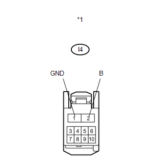
(b) Measure the resistance and voltage according to the value(s) in the table below.
Standard Resistance:
|
Tester Connection |
Condition |
Specified Condition |
|---|---|---|
|
I4-1 (GND) - Body ground |
Always |
Below 1 Ω |
Standard Voltage:
|
Tester Connection |
Condition |
Specified Condition |
|---|---|---|
|
I4-2 (B) - Body ground |
Always |
11 to 14 V |
|
*1 |
Front view of wire harness connector (to Power Window Regulator Motor Assembly (for Driver Side)) |
| NG | |
REPAIR OR REPLACE HARNESS OR CONNECTOR |
|
|
3. |
CHECK HARNESS AND CONNECTOR (MASTER SWITCH - POWER WINDOW REGULATOR MOTOR ASSEMBLY) |
|
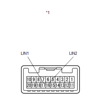
(a) Disconnect the I6 switch connector. |
|
.png)
(b) Measure the resistance according to the value(s) in the table below.
Standard Resistance:
|
Tester Connection |
Condition |
Specified Condition |
|---|---|---|
|
I6-16 (LIN2) - I4-9 (LIN) |
Always |
Below 1 Ω |
|
I6-16 (LIN2) - Body ground |
Always |
10 kΩ or higher |
|
*1 |
Front view of wire harness connector (to Multiplex Network Master Switch Assembly) |
|
*2 |
Front view of wire harness connector (to Power Window Regulator Motor Assembly (for Driver Side)) |
| NG | |
REPAIR OR REPLACE HARNESS OR CONNECTOR |
|
|
4. |
INSPECT MULTIPLEX NETWORK MASTER SWITCH ASSEMBLY |
|
(a) Remove the multiplex network master switch assembly (See page
|
|
(b) Measure the resistance according to the value(s) in the table below.
Standard Resistance:
|
Tester Connection |
Condition |
Specified Condition |
|---|---|---|
|
16 (LIN2) - 17 (LIN1) |
Always |
Below 1 Ω |
|
*1 |
Component without harness connected (Multiplex Network Master Switch Assembly) |
| NG | |
REPLACE MULTIPLEX NETWORK MASTER SWITCH ASSEMBLY |
|
|
5. |
REPLACE POWER WINDOW REGULATOR MOTOR ASSEMBLY (for DRIVER SIDE) |
(a) Replace the power window regulator motor assembly (for driver side) (See
page ).
|
|
6. |
CHECK DTC OUTPUT |
(a) Clear the DTC (See page ).
(b) Recheck for DTCs.
OK:
DTC B2321 is not output.
| OK | |
END (POWER WINDOW REGULATOR MOTOR ASSEMBLY WAS DEFECTIVE) |
| NG | |
REPLACE MAIN BODY ECU (DRIVER SIDE JUNCTION BLOCK ASSEMBLY) |
 Rear Door RH ECU Communication Stop (B2323)
DESCRIPTION
This DTC is stored when LIN communication between the power window regulator
motor assembly (for rear RH side) and main body ECU (driver side junction block
assembly) stops for more t ...
 Sliding Roof ECU Communication Stop (B1273)
DESCRIPTION
This DTC is stored when LIN communication between the sliding roof ECU (sliding
roof drive gear sub-assembly) and main body ECU (driver side junction block assembly)
stops for more th ...
Other materials about Toyota Venza:
Power Source Control ECU Malfunction (B2782)
DESCRIPTION
The power management control ECU controls the power supply to activate the steering
lock motor. This prevents the steering wheel from being locked while the vehicle
is moving.
DTC No.
DTC Detecting Condition
T ...
Noise Occurs
PROCEDURE
1.
CHECK NOISE CONDITION
(a) Check from which direction the noise comes (front left or right, or rear
left or right).
OK:
The location of the noise source can be determined.
NG
GO TO STEP 3
...
Installation
INSTALLATION
PROCEDURE
1. TEMPORARILY INSTALL SLIDING ROOF HOUSING ASSEMBLY
(a) Temporarily install the sliding roof housing panel with the 18 nuts.
NOTICE:
When installing the housing to the vehicle, first install the housing
center front and ...

0.1179