Toyota Venza: Headlight Solenoid Circuit
DESCRIPTION
- for HID Headlight:
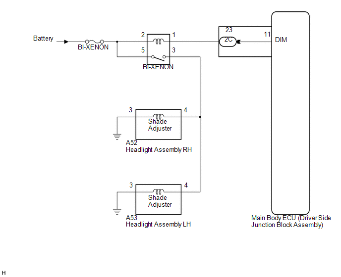
When the main body ECU receives a high beam turn on signal, the main body ECU activates the bi-function by controlling the BI-XENON relay. The bi-function increases the upper illumination area of the discharge bulb (low beam) by moving a shade using a solenoid built into the headlight unit.
WIRING DIAGRAM
CAUTION / NOTICE / HINT
NOTICE:
Inspect the fuses for circuits related to this system before performing the following inspection procedure.
PROCEDURE
|
1. |
CHECK OPERATION (LOW BEAM HEADLIGHTS) |
(a) Check the operation of the low beam headlights.
OK:
Low beam headlights operate normally.
| NG | .gif) |
GO TO PROBLEM SYMPTOMS TABLE |
|
.gif)
|
2. |
PERFORM ACTIVE TEST USING TECHSTREAM |
(a) Connect the Techstream to the DLC3.
(b) Turn the ignition switch to ON.
(c) Turn the Techstream on.
(d) Enter the following menus: Body Electrical / Main Body / Active Test.
(e) Check that the high beam headlights illuminate.
Main Body|
Tester Display |
Test Part |
Control Range |
Diagnostic Note |
|---|---|---|---|
|
Head Light Hi |
High beam headlight relay |
ON/OFF |
- |
OK:
High beam headlights illuminate.
| OK | |
PROCEED TO NEXT SUSPECTED AREA SHOWN IN PROBLEM SYMPTOMS TABLE |
|
|
3. |
INSPECT BI-XENON RELAY (BI-XENON) |
|
(a) Remove the BI-XENON relay from the power distributor (engine room junction block assembly). |
|
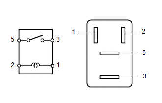
(b) Measure the resistance according to the value(s) in the table below.
Standard Resistance:
|
Tester Connection |
Condition |
Specified Condition |
|---|---|---|
|
3 - 5 |
Battery voltage applied to terminals 1 and 2 |
Below 1 Ω |
|
3 - 5 |
Battery voltage not applied between terminals |
10 kΩ or higher |
| NG | |
REPLACE BI-XENON RELAY |
|
|
4. |
CHECK HARNESS AND CONNECTOR (BATTERY - BI-XENON RELAY) |
(a) Measure the voltage according to the value(s) in the table below.
Standard Voltage:
|
Tester Connection |
Condition |
Specified Condition |
|---|---|---|
|
Relay terminal 2 - Body ground |
Always |
11 to 14 V |
|
Relay terminal 5 - Body ground |
Always |
11 to 14 V |
| NG | |
REPAIR OR REPLACE HARNESS OR CONNECTOR |
|
|
5. |
CHECK HARNESS AND CONNECTOR (BI-XENON RELAY - HEADLIGHT ASSEMBLY) |
(a) Disconnect the A53 headlight assembly LH connector.
(b) Disconnect the A52 headlight assembly RH connector.
(c) Measure the resistance according to the value(s) in the table below.
Standard Resistance:
|
Tester Connection |
Condition |
Specified Condition |
|---|---|---|
|
Relay terminal 3 - A53-4 |
Always |
Below 1 Ω |
|
Relay terminal 3 - A52-4 |
Always |
Below 1 Ω |
|
Relay terminal 3 - Body ground |
Always |
10 kΩ or higher |
| NG | |
REPAIR OR REPLACE HARNESS OR CONNECTOR |
|
|
6. |
CHECK HARNESS AND CONNECTOR (BI-XENON RELAY - DRIVER SIDE JUNCTION BLOCK) |
(a) Disconnect the 2C main body ECU (driver side junction block assembly) connector.
(b) Measure the resistance according to the value(s) in the table below.
Standard Resistance:
|
Tester Connection |
Condition |
Specified Condition |
|---|---|---|
|
Relay terminal 1 - 2C-23 |
Always |
Below 1 Ω |
|
2C-23 - Body ground |
Always |
10 kΩ or higher |
| OK | |
REPLACE MAIN BODY ECU (DRIVER SIDE JUNCTION BLOCK ASSEMBLY) |
| NG | |
REPAIR OR REPLACE HARNESS OR CONNECTOR |
 Headlight Relay Circuit
DESCRIPTION
The main body ECU (driver side junction block assembly) controls the headlight
relays.
WIRING DIAGRAM
CAUTION / NOTICE / HINT
NOTICE:
Inspect the fuses for circuits related to t ...
 Daytime Running Light Relay Circuit
DESCRIPTION
The main body ECU (driver side junction block assembly) controls the daytime
running lights.
WIRING DIAGRAM
1. for Halogen Headlight
2. for HID Headlight
PROCEDURE
1 ...
Other materials about Toyota Venza:
Transmitter ID1 Operation Stop (C2111/11-C2114/14)
DESCRIPTION
The tire pressure warning valve and transmitter installed in each tire and wheel
assembly measures the tire pressures. The measured values are transmitted as radio
waves to the tire pressure warning antenna and receiver on the body and then se ...
Components
COMPONENTS
ILLUSTRATION
ILLUSTRATION
ILLUSTRATION
ILLUSTRATION
ILLUSTRATION
ILLUSTRATION
ILLUSTRATION
ILLUSTRATION
ILLUSTRATION
ILLUSTRATION
ILLUSTRATION
ILLUSTRATION
...
Skid Control ECU Communication Stop Mode
DESCRIPTION
Detection Item
Symptom
Trouble Area
Skid Control ECU Communication Stop Mode
"ABS/VSC/TRAC" is not displayed on "CAN Bus Check" screen of
the Techstr ...

0.1455