Toyota Venza: Clearance Sonar Main Switch Circuit
DESCRIPTION
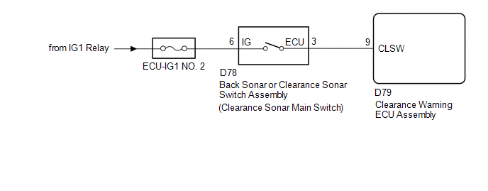
The back sonar or clearance sonar switch assembly is installed at the base of the driver side of the instrument panel.
When the clearance sonar main switch is turned on, an on signal is sent to the clearance warning ECU assembly. The intuitive parking assist system operates according to this signal.
WIRING DIAGRAM
CAUTION / NOTICE / HINT
NOTICE:
Inspect the fuses for circuits related to this system before performing the following inspection procedure.
PROCEDURE
|
1. |
READ VALUE USING TECHSTREAM |
(a) Connect the Techstream to the DLC3.
(b) Turn the engine switch on (IG).
(c) Turn the Techstream on.
(d) Enter the following menus: Body Electrical / Intuitive P/A / Data List.
(e) According to the display on the Techstream, read the Data List.
Intuitive P/A|
Tester Display |
Measurement Item/Range |
Normal Condition |
Diagnostic Note |
|---|---|---|---|
|
Main Switch |
Clearance sonar main switch/OFF or ON |
OFF: Clearance sonar main switch off ON: Clearance sonar main switch on |
- |
|
Clearance Sonar ECU Type |
Type of clearance sonar ECU/Normal |
Normal: Normal clearance sonar type |
- |
|
Result |
Proceed to |
|---|---|
|
Both of the following conditions are met:
|
A |
|
"Normal" is not displayed. |
B |
|
Both of the following conditions are met:
|
C |
| A | .gif) |
PROCEED TO NEXT SUSPECTED AREA SHOWN IN PROBLEM SYMPTOMS TABLE |
| B | |
REPLACE CLEARANCE WARNING ECU ASSEMBLY |
|
.gif)
|
2. |
INSPECT BACK SONAR OR CLEARANCE SONAR SWITCH ASSEMBLY |
(a) Remove the back sonar or clearance sonar switch assembly (See page
.gif) ).
).
|
(b) Measure the resistance according to the value(s) in the table below. Standard Resistance:
|
|
.png)
| NG | |
REPLACE BACK SONAR OR CLEARANCE SONAR SWITCH ASSEMBLY |
|
|
3. |
CHECK HARNESS AND CONNECTOR (BACK SONAR OR CLEARANCE SONAR SWITCH ASSEMBLY POWER SOURCE) |
(a) Measure the voltage according to the value(s) in the table below.
Standard Voltage:
|
Tester Connection |
Condition |
Specified Condition |
|---|---|---|
|
D78-6 (IG) - Body ground |
Engine switch on (IG) |
11 to 14 V |
|
D78-6 (IG) - Body ground |
Engine switch off |
Below 1 V |
| NG | |
REPAIR OR REPLACE HARNESS OR CONNECTOR |
|
|
4. |
CHECK HARNESS AND CONNECTOR (BACK SONAR OR CLEARANCE SONAR SWITCH ASSEMBLY - CLEARANCE WARNING ECU ASSEMBLY) |
(a) Disconnect the D79 clearance warning ECU assembly connector.
(b) Measure the resistance according to the value(s) in the table below.
Standard Resistance:
|
Tester Connection |
Condition |
Specified Condition |
|---|---|---|
|
D79-9 (CLSW) - D78-3 (ECU) |
Always |
Below 1 Ω |
|
D79-9 (CLSW) - Body ground |
Always |
10 kΩ or higher |
| OK | |
REPLACE CLEARANCE WARNING ECU ASSEMBLY |
| NG | |
REPAIR OR REPLACE HARNESS OR CONNECTOR |
 Front Right Sensor Malfunction (C1AE4)
DESCRIPTION
The No. 1 ultrasonic sensor (front right sensor) is installed on the front bumper.
The ECU detects obstacles based on signals received from the No. 1 ultrasonic sensor
(front right se ...
 Clearance Warning Buzzer Circuit
DESCRIPTION
This circuit consists of the No. 1 clearance warning buzzer and clearance warning
ECU assembly. An ECU-excited type buzzer is used. The ECU operates the buzzer using
a sound pattern t ...
Other materials about Toyota Venza:
Open or Short Circuit in ABS Motor Relay Circuit (C0273/13)
DESCRIPTION
The ABS motor relay supplies power to the ABS pump motor. While the ABS is activated,
the ECU turns the motor relay on and operates the ABS pump motor.
If the voltage supplied to the motor relay (+BM) is below the DTCs detection
threshold due ...
Dtc Check / Clear
DTC CHECK / CLEAR
1. CHECK DTC
(a) Connect the Techstream to the DLC3.
(b) Turn the ignition switch to ON.
(c) Turn the Techstream on.
(d) Enter the following menus: Powertrain / Cruise Control / DTC.
(e) Check the details of the DTC(s) (See page
).
2 ...
Rear Door RH ECU Communication Stop (B2323)
DESCRIPTION
This DTC is stored when LIN communication between the power window regulator
motor assembly (for rear RH side) and main body ECU (driver side junction block
assembly) stops for more than 10 seconds.
DTC No.
DTC Detection ...

0.1652