Toyota Venza: Crankshaft Position - Camshaft Position Correlation (Bank 1 Sensor A) (P0016,P0017)
DESCRIPTION
In the VVT (Variable Valve Timing) system, the appropriate intake and exhaust valve open and close timing is controlled by the ECM. The ECM performs intake and exhaust valve control by performing the following: 1) controlling the camshaft and camshaft timing oil control valve assembly, and operating the camshaft timing gear; and 2) changing the relative positions of the camshaft and crankshaft.
|
DTC No. |
Detection Condition |
Trouble Area |
|---|---|---|
|
P0016 |
Deviation in crankshaft position sensor signal and camshaft position sensor (for intake camshaft) signal (2 trip detection logic) |
|
|
P0017 |
Deviation in crankshaft position sensor signal and camshaft position sensor (for exhaust camshaft) signal (2 trip detection logic) |
|
MONITOR DESCRIPTION
To monitor the correlation of the intake camshaft position and crankshaft position, the ECM checks the VVT learned value while the engine is idling. The VVT learned value is calibrated based on the camshaft position and crankshaft position. The intake valve timing is set to the most retarded angle while the engine is idling. If the VVT learned value is out of the specified range in consecutive driving cycles, the ECM illuminates the MIL and stores DTC P0016.
To monitor the correlation of the exhaust camshaft position and crankshaft position, the ECM checks the VVT learned value while the engine is idling. The VVT learned value is calibrated based on the camshaft position and crankshaft position. The exhaust valve timing is set to the most advanced angle while the engine is idling. If the VVT learned value is out of the specified range in consecutive driving cycles, the ECM illuminates the MIL and stores DTC P0017.
MONITOR STRATEGY
|
Related DTCs |
P0016: Camshaft Timing Misalignment at Idling (for Intake Camshaft) P0017: Camshaft Timing Misalignment at Idling (for Exhaust Camshaft) |
|
Required Sensors/Components (Main) |
Camshaft timing gear assembly Camshaft timing exhaust gear assembly |
|
Required Sensors/Components (Related) |
Camshaft position sensor Crankshaft position sensor |
|
Frequency of Operation |
Continuous |
|
Duration |
Less than 1 minute |
|
MIL Operation |
2 driving cycles |
|
Sequence of Operation |
None |
TYPICAL ENABLING CONDITIONS
P0016: Intake Camshaft|
Monitor runs whenever following DTCs not stored |
P0010 (Camshaft Timing Oil Control Valve) P0102, P0103 (Mass Air Flow Meter) P0115, P0117, P0118 (Engine Coolant Temperature Sensor) P0125 (Insufficient Coolant Temperature for Closed Loop Fuel Control) P0335 (Crankshaft Position Sensor) P0340 (Camshaft Position Sensor) |
|
Engine speed |
500 to 1000 rpm |
|
Monitor runs whenever following DTCs not stored |
P0013 (Exhaust Camshaft Timing Oil Control Valve) P0102, P0103 (Mass Air Flow Meter) P0115, P0117, P0118 (Engine Coolant Temperature Sensor) P0125 (Insufficient Coolant Temperature for Closed Loop Fuel Control) P0335 (Crankshaft Position Sensor) P0340 (Camshaft Position Sensor) |
|
Engine speed |
500 to 1000 rpm |
TYPICAL MALFUNCTION THRESHOLDS
P0016: Intake Camshaft|
Either of following conditions is met |
1 or 2 |
|
1. VVT learned value at maximum retarded valve timing |
Less than 22°CA (Crankshaft Angle) |
|
2. VVT learned value at maximum retarded valve timing |
More than 47°CA (Crankshaft Angle) |
|
Either of following conditions is met |
1 or 2 |
|
1. VVT learned value at maximum advanced valve timing |
Less than 82.5°CA (Crankshaft Angle) |
|
2. VVT learned value at maximum advanced valve timing |
More than 107.5°CA (Crankshaft Angle) |
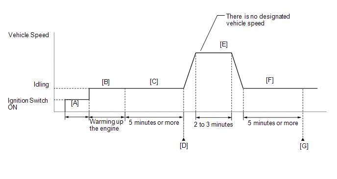
CONFIRMATION DRIVING PATTERN
- Connect the Techstream to the DLC3.
- Turn the ignition switch to ON and turn the Techstream on.
- Clear the DTCs (even if no DTCs are stored, perform the clear DTC procedure)
(See page
.gif) ).
). - Turn the ignition switch off and wait for at least 30 seconds.
- Turn the ignition switch to ON and turn the Techstream on [A].
- Start the engine and warm it up until the engine coolant temperature reaches 75°C (167°F) or higher [B].
- Idle the engine for 5 minutes or more [C].
- Enter the following menus: Powertrain / Engine / Trouble Codes.
- Read the Pending DTCs [G].
HINT:
- If a pending DTC is output, the system is malfunctioning.
- If a pending DTC is not output, perform the following procedure.
- Enter the following menus: Powertrain / Engine / Utility / All Readiness.
- Input the DTC: P0016 or P0017.
- Check the DTC judgment result [D].
Techstream Display
Description
NORMAL
- DTC judgment completed
- System normal
ABNORMAL
- DTC judgment completed
- System abnormal
INCOMPLETE
- DTC judgment not completed
- Perform driving pattern after confirming DTC enabling conditions
N/A
- Unable to perform DTC judgment
- Number of DTCs which do not fulfill DTC preconditions has reached ECU memory limit
HINT:
- If the judgment result shows NORMAL, the system is normal.
- If the judgment result shows ABNORMAL, the system has a malfunction.
- If the judgment result shows INCOMPLETE or N/A, perform steps [E] through [G].
- Drive the vehicle for 2 to 3 minutes [E].
CAUTION:
When performing the confirmation driving pattern, obey all speed limits and traffic laws.
- Idle the engine for 5 minutes or more [F].
- Check the DTC judgment result [G].
- If the test result is INCOMPLETE or N/A and no pending DTC is output,
perform a universal trip and check for permanent DTCs (See page
).
HINT:
- If a permanent DTC is output, the system is malfunctioning.
- If no permanent DTC is output, the system is normal.
CAUTION / NOTICE / HINT
HINT:
- The monitor for this DTC detects when the timing chain is shifted by one tooth or more.
- Read freeze frame data using the Techstream. The ECM records vehicle and driving condition information as freeze frame data the moment a DTC is stored. When troubleshooting, freeze frame data can help determine if the vehicle was moving or stationary, if the engine was warmed up or not, if the air fuel ratio was lean or rich, and other data from the time the malfunction occurred.
PROCEDURE
|
1. |
CHECK ANY OTHER DTCS OUTPUT (IN ADDITION TO DTC P0016 AND P0017) |
(a) Connect the Techstream to the DLC3.
(b) Turn the ignition switch to ON.
(c) Turn the Techstream on.
(d) Enter the following menus: Powertrain / Engine / Trouble Codes.
(e) Read the DTCs.
|
Result |
Proceed to |
|---|---|
|
DTC P0016 or P0017 is output |
A |
|
DTC P0016 or P0017 and other DTCs are output |
B |
HINT:
If any DTCs other than P0016 or P0017 are output, troubleshoot those DTCs first.
| B | .gif) |
GO TO DTC CHART |
|
.gif)
|
2. |
PERFORM ACTIVE TEST USING TECHSTREAM (OPERATE CAMSHAFT TIMING OIL CONTROL VALVE ASSEMBLY) |
(a) Connect the Techstream to the DLC3.
(b) Start the engine.
(c) Turn the Techstream on.
(d) Check the camshaft timing oil control valve assembly for intake camshaft.
(1) Enter the following menus: Powertrain / Engine / Active Test / Control the VVT Linear (Bank 1).
(2) Check the engine speed while operating the camshaft timing oil control valve assembly (for intake camshaft) using the Techstream.
OK:
|
Techstream Operation |
Specified Condition |
|---|---|
|
0% |
Normal engine speed |
|
100% |
Engine idles roughly or stalls |
HINT:
If the result is not acceptable, cool the engine (engine coolant temperature is 50°C (122°F) or less) and perform the Active Test again.
(e) Check the camshaft timing oil control valve assembly for exhaust camshaft.
(1) Enter the following menus: Powertrain / Engine / Active Test / Control the VVT Exhaust Linear (Bank 1).
(2) Check the engine speed while operating the camshaft timing oil control valve assembly (for exhaust camshaft) using the Techstream.
OK:
|
Techstream Operation |
Specified Condition |
|---|---|
|
0% |
Normal engine speed |
|
100% |
Engine idles roughly or stalls |
HINT:
If the result is not acceptable, cool the engine (engine coolant temperature is 50°C (122°F) or less) and perform the Active Test again.
| NG | |
GO TO STEP 4 |
|
|
3. |
CHECK WHETHER DTC OUTPUT RECURS (DTC P0016 OR P0017) |
(a) Connect the Techstream to the DLC 3.
(b) Turn the ignition switch to ON.
(c) Turn the Techstream on.
(d) Clear the DTCs (See page ).
(e) Turn the ignition switch off and wait for at least 30 seconds.
(f) Turn the ignition switch to ON and turn the Techstream on.
(g) Start the engine.
(h) Drive the vehicle in accordance with the driving pattern described in the Confirmation Driving Pattern.
(i) Enter the following menus: Powertrain / Engine / Trouble Codes / Pending.
(j) Read the pending DTCs.
|
Result |
Proceed to |
|---|---|
|
DTC is not output |
A |
|
DTC P0016 or P0017 is output |
B |
HINT:
DTC P0016 or P0017 may be stored when foreign objects in the engine oil are caught in some parts of the system. The DTC will remain stored even if the system returns to normal after a short time. These foreign objects may then be captured by the oil filter.
| A | |
CHECK FOR INTERMITTENT PROBLEMS |
|
|
4. |
INSPECT CAMSHAFT TIMING OIL CONTROL VALVE ASSEMBLY (FOR INTAKE OR EXHAUST CAMSHAFT) |
HINT:
Inspect the specified camshaft timing oil control valve assembly (for intake or exhaust camshaft) in accordance with the inspection result of step 2.
(a) Inspect the camshaft timing oil control valve assembly (for intake or exhaust
camshaft) (See page ).
| NG | |
REPLACE CAMSHAFT TIMING OIL CONTROL VALVE ASSEMBLY (INTAKE OR EXHAUST CAMSHAFT) |
|
|
5. |
CHECK VALVE TIMING |
| NG | |
GO TO STEP 9 |
|
|
6. |
INSPECT OIL CONTROL VALVE FILTER |
| NG | |
REPLACE OIL CONTROL VALVE FILTER |
|
|
7. |
REPLACE CAMSHAFT TIMING GEAR ASSEMBLY OR CAMSHAFT TIMING EXHAUST GEAR ASSEMBLY |
(a) Replace the camshaft timing gear assembly or camshaft timing exhaust gear
assembly (See page ).
HINT:
Perform "Inspection After Repair" after replacing the camshaft timing gear assembly
or camshaft timing exhaust gear assembly (See page
).
|
|
8. |
CHECK WHETHER DTC OUTPUT RECURS (DTC P0016 OR P0017) |
(a) Connect the Techstream to the DLC 3.
(b) Turn the ignition switch to ON.
(c) Turn the Techstream on.
(d) Clear the DTCs (See page ).
(e) Turn the ignition switch off and wait for at least 30 seconds.
(f) Turn the ignition switch to ON and turn the Techstream on.
(g) Start the engine.
(h) Drive the vehicle in accordance with the driving pattern described in the Confirmation Driving Pattern.
(i) Enter the following menus: Powertrain / Engine / Trouble Codes / Pending.
(j) Read the pending DTCs.
|
Result |
Proceed to |
|---|---|
|
DTC is not output |
A |
|
DTC P0016 or P0017 is output |
B |
| A | |
END |
| B | |
REPLACE ECM |
|
9. |
CHECK ENGINE MECHANICAL SYSTEM |
| NG | |
REPAIR OR REPLACE MALFUNCTIONING PARTS, COMPONENT AND AREA |
|
|
10. |
CHECK WHETHER DTC OUTPUT RECURS |
(a) Connect the Techstream to the DLC 3.
(b) Turn the ignition switch to ON.
(c) Turn the Techstream on.
(d) Clear the DTCs (See page ).
(e) Turn the ignition switch off and wait for at least 30 seconds.
(f) Turn the ignition switch to ON and turn the Techstream on.
(g) Start the engine.
(h) Drive the vehicle in accordance with the driving pattern described in the Confirmation Driving Pattern.
(i) Enter the following menus: Powertrain / Engine / Trouble Codes / Pending.
(j) Read the pending DTCs.
|
Result |
Proceed to |
|---|---|
|
DTC is not output |
A |
|
DTC P0016 or P0017 is output |
B |
| A | |
CHECK FOR INTERMITTENT PROBLEMS |
| B | |
REPLACE ECM |
 Camshaft Position "B" - Timing Over-Advanced or System Performance (Bank 1)
(P0014,P0015)
Camshaft Position "B" - Timing Over-Advanced or System Performance (Bank 1)
(P0014,P0015)
DESCRIPTION
Refer to DTC P0013 (See page ).
DTC No.
DTC Detection Condition
Trouble Area
P0014
The valve timing is stuck at a certain va ...
 Oxygen (A/F) Sensor Heater Control Circuit Low (Bank 1 Sensor 1) (P0031,P0032,P101D)
DESCRIPTION
Refer to DTC P2195 (See page ).
HINT:
When any of these DTCs is stored, the ECM enters fail-safe mode. The
ECM turns off the air fuel ratio sensor heater in fail-safe mode. ...
Other materials about Toyota Venza:
Back Door Opener Switch
Components
COMPONENTS
ILLUSTRATION
Removal
REMOVAL
PROCEDURE
1. REMOVE BACK DOOR PANEL TRIM ASSEMBLY
2. REMOVE REAR LIGHT ASSEMBLY LH
3. REMOVE REAR LIGHT ASSEMBLY RH
HINT:
Use the same procedure for the RH side and LH side.
4. REMOVE BA ...
On-vehicle Inspection
ON-VEHICLE INSPECTION
PROCEDURE
1. INSPECT WINDSHIELD WIPER MOTOR ASSEMBLY
(a) for RH Side
(1) Operate the windshield wiper motor assembly.
(2) Stop the windshield wiper motor assembly operation.
...
Reassembly
REASSEMBLY
PROCEDURE
1. INSTALL BRAKE MASTER CYLINDER RESERVOIR ASSEMBLY
(a) Apply a light layer of lithium soap base glycol grease to the entire circumference
of 2 new brake master cylinder reservoir grommets.
(b) Install the 2 brake master cylinder res ...

0.1365