Toyota Venza: Components
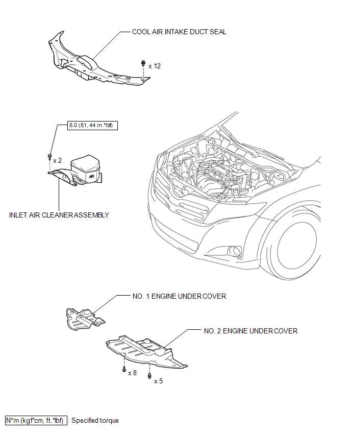
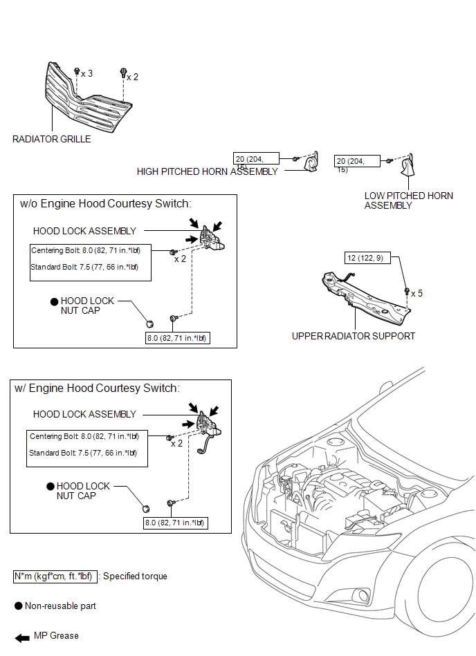
COMPONENTS
ILLUSTRATION
ILLUSTRATION
ILLUSTRATION
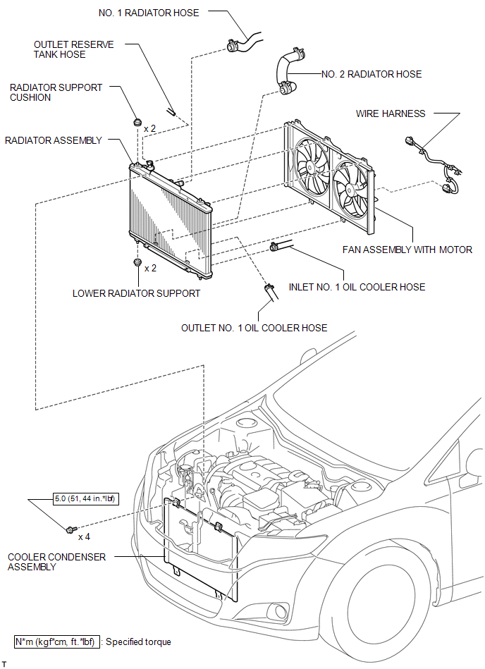
 Radiator
...
 On-vehicle Inspection
ON-VEHICLE INSPECTION
PROCEDURE
1. CHECK RADIATOR CAP SUB-ASSEMBLY
(a) Measure the valve opening pressure.
(1) If there are water stains or foreign matter on rubber packings 1, 2 or 3,
clean t ...
Other materials about Toyota Venza:
Personal Light
Components
COMPONENTS
ILLUSTRATION
Removal
REMOVAL
PROCEDURE
1. REMOVE MAP LIGHT ASSEMBLY
(a) Using a moulding remover, disengage the 2 claws and 2 clips.
Text in Illustration
*1
Fastener
...
Throttle / Pedal Position Sensor / Switch "A" Circuit Malfunction (P0120-P0123,P0220,P0222,P0223,P2135)
DESCRIPTION
HINT:
These DTCs relate to the throttle position sensor.
The throttle position sensor is mounted on the throttle body, and detects the
opening angle of the throttle valve. This sensor is a non-contact type sensor. It
uses hall-effect element ...
Knock Sensor
Components
COMPONENTS
ILLUSTRATION
Removal
REMOVAL
PROCEDURE
1. REMOVE INTAKE MANIFOLD
(a) Remove the intake manifold (See page ).
2. REMOVE KNOCK SENSOR
(a) Disconnect the sensor connector.
...

0.1674