Toyota Venza: Components
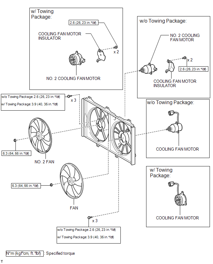
COMPONENTS
ILLUSTRATION

 On-vehicle Inspection
ON-VEHICLE INSPECTION
PROCEDURE
1. INSPECT COOLING FAN MOTOR
(a) Check that the motor operates smoothly when the battery is connected
to the cooling fan motor connector.
Text in I ...
Other materials about Toyota Venza:
Components
COMPONENTS
ILLUSTRATION
ILLUSTRATION
ILLUSTRATION
ILLUSTRATION
ILLUSTRATION
ILLUSTRATION
ILLUSTRATION
...
On-vehicle Inspection
ON-VEHICLE INSPECTION
PROCEDURE
1. INSPECT GARAGE DOOR OPENER
(a) To inspect the garage door opener system, press each switch and check
that the LED in the "HomeLink" logo illuminates as illustrated. If one or
more of the switch ...
Problem Symptoms Table
PROBLEM SYMPTOMS TABLE
HINT:
Use the table below to help determine the cause of problem symptoms.
If multiple suspected areas are listed, the potential causes of the symptoms
are listed in order of probability in the "Suspected Area" ...
© 2016-2026 Copyright www.tovenza.com

0.116
0.116