Toyota Venza: Components
COMPONENTS
ILLUSTRATION
ILLUSTRATION
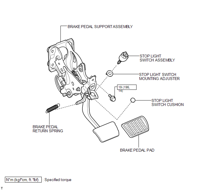
 Brake Pedal
...
 Removal
REMOVAL
PROCEDURE
1. REMOVE BRAKE BOOSTER ASSEMBLY
HINT:
Refer to the instructions for Removal of the brake booster assembly (See page
).
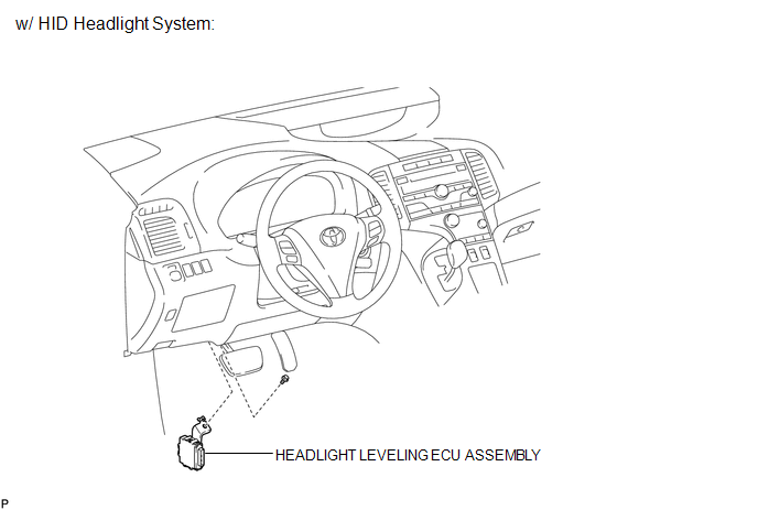
2. REMOVE HEADLIGHT LEVELING ECU ASSEMBLY (w/ HID Headl ...
Other materials about Toyota Venza:
System Description
SYSTEM DESCRIPTION
1. POWER BACK DOOR SYSTEM DESCRIPTION
(a) The power back door system controls the power back door by automatically
opening and closing the power back door with a motor.
(1) The power back door system operates only when the necessary con ...
Control Module Performance (P0607)
MONITOR DESCRIPTION
The ECM continuously monitors its internal processors (CPUs) and heated oxygen
sensor transistors. This self-check ensures that the ECM is functioning properly.
DTC No.
DTC Detection Condition
Trouble Ar ...
Cleaning and protecting the vehicle exterior
Perform the following to protect the vehicle and maintain it in prime condition.
• Working from top to bottom, liberally apply water to the vehicle body, wheel
wells and underside of the vehicle to remove any dirt and dust.
Wash the vehicle body using a ...

0.1692