Toyota Venza: Removal
REMOVAL
PROCEDURE
1. REMOVE BRAKE BOOSTER ASSEMBLY
HINT:
Refer to the instructions for Removal of the brake booster assembly (See page
.gif) ).
).
2. REMOVE HEADLIGHT LEVELING ECU ASSEMBLY (w/ HID Headlight System)
3. REMOVE STOP LIGHT SWITCH ASSEMBLY
4. REMOVE STOP LIGHT SWITCH MOUNTING ADJUSTER
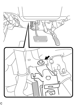
5. REMOVE BRAKE PEDAL SUPPORT ASSEMBLY
|
(a) Disconnect the connector. |
|

|
(b) Remove the bolt and brake pedal support assembly from the instrument panel reinforcement. |
|
 Components
COMPONENTS
ILLUSTRATION
ILLUSTRATION
...
 Disassembly
DISASSEMBLY
PROCEDURE
1. REMOVE BRAKE PEDAL RETURN SPRING
(a) Remove the brake pedal return spring from the brake pedal support
assembly.
...
Other materials about Toyota Venza:
Rear Occupant Classification Sensor RH Collision Detection (B1788)
DESCRIPTION
DTC B1788 is output when the occupant classification ECU receives a collision
detection signal sent by the rear occupant classification sensor RH if an accident
occurs.
DTC B1788 is also output when the front seat assembly RH is subjected to ...
Removal
REMOVAL
PROCEDURE
1. REMOVE NO. 1 SLIDING ROOF GLASS SUB-ASSEMBLY
(a) Fully open the No. 2 sliding roof glass sub-assembly.
(b) Using a T20 "TORX" socket wrench, remove the 6 screws and No. 1 sliding
roof glass sub-assembly.
...
Removal
REMOVAL
PROCEDURE
1. PRECAUTION
NOTICE:
After turning the ignition switch off, waiting time may be required before disconnecting
the cable from the negative (-) battery terminal. Therefore, make sure to read the
disconnecting the cable from the negativ ...

0.1539