Toyota Venza: Components
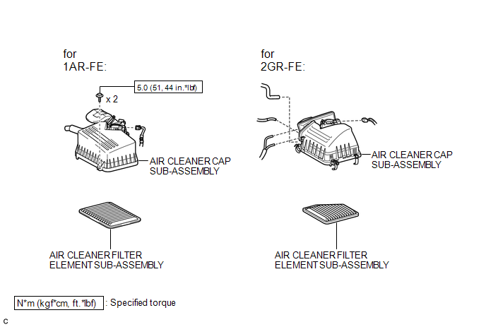
COMPONENTS
ILLUSTRATION
ILLUSTRATION
.png)
ILLUSTRATION

 Disassembly
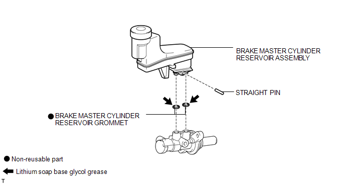
DISASSEMBLY
PROCEDURE
1. REMOVE BRAKE MASTER CYLINDER RESERVOIR ASSEMBLY
(a) Mount the brake master cylinder sub-assembly in a vise.
NOTICE:
Place aluminum plates on the vise to prevent damage to ...
Other materials about Toyota Venza:
Portable Player cannot be Operated Using In-vehicle Device or Track Information
is not Displayed on In-vehicle Device
PROCEDURE
1.
CHECK USING ANOTHER "Bluetooth" AUDIO COMPATIBLE VEHICLE OF SAME MODEL
(a) Check if track information is displayed normally on another "Bluetooth" audio
compatible vehicle of the same model.
...
Clearance Warning Ecu
Components
COMPONENTS
ILLUSTRATION
Removal
REMOVAL
PROCEDURE
1. REMOVE FRONT DOOR SCUFF PLATE RH
2. REMOVE COWL SIDE TRIM SUB-ASSEMBLY RH
3. REMOVE NO. 2 INSTRUMENT PANEL UNDER COVER SUB-ASSEMBLY
4. REMOVE LOWER INSTRUMENT PANEL SUB-ASS ...
IG Signal Circuit
DESCRIPTION
This circuit detects the ignition switch ON or off condition, and sends it to
the main body ECU (driver side junction block assembly).
WIRING DIAGRAM
CAUTION / NOTICE / HINT
NOTICE:
Inspect the fuses for circuits related to this system b ...

0.1715