Toyota Venza: Components
COMPONENTS
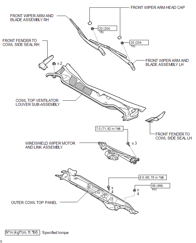
ILLUSTRATION
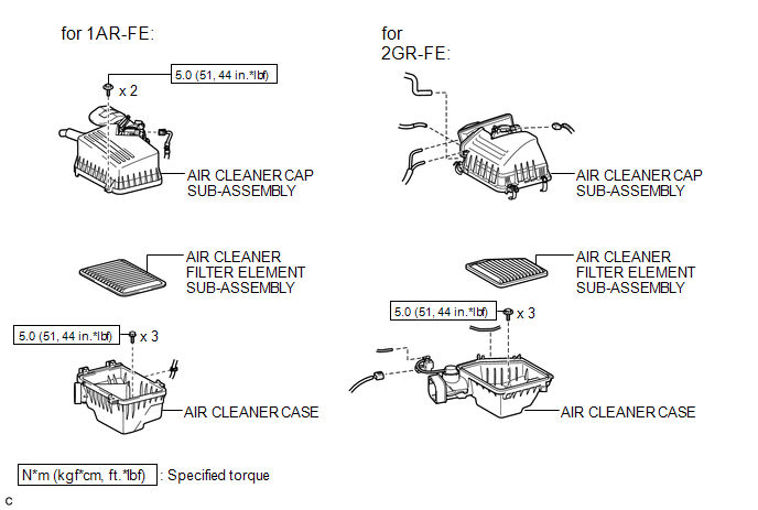
ILLUSTRATION
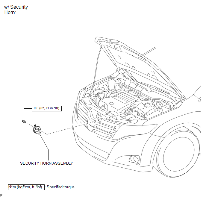
ILLUSTRATION
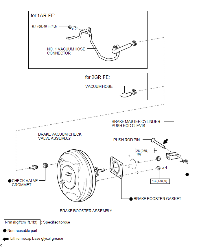
ILLUSTRATION

ILLUSTRATION
 Brake Booster
...
 On-vehicle Inspection
ON-VEHICLE INSPECTION
PROCEDURE
1. INSPECT BRAKE BOOSTER ASSEMBLY
(a) Airtightness check
(1) Start the engine and stop it after 1 or 2 minutes. Slowly depress
the brake pedal seve ...
Other materials about Toyota Venza:
System Diagram
SYSTEM DIAGRAM
Input and Output Signal of Each ECU
Transmitting ECU (transmitter)
Receiving ECU
Signal
Communication Method
Power management Control ECU
Steering Lock ECU (Steering Lock ...
Precaution
PRECAUTION
NOTICE:
When disconnecting the cable from the negative (-) battery terminal, initialize
the following systems after the cable is reconnected.
System Name
See Procedure
Back Door Closer System
...
Seat Position Sensor
Components
COMPONENTS
ILLUSTRATION
On-vehicle Inspection
ON-VEHICLE INSPECTION
CAUTION / NOTICE / HINT
CAUTION:
Be sure to follow the correct removal and installation procedures of the seat
position sensor.
PROCEDURE
1. INSPECT SEAT POSITION S ...

0.1208