Toyota Venza: Room Temperature Sensor Circuit (B1411/11)
DESCRIPTION
The room temperature sensor is installed in the instrument panel. It detects the cabin temperature to control the air conditioning AUTO mode. The resistance of the room temperature sensor changes in accordance with the cabin temperature. As the temperature decreases, the resistance increases. As the temperature increases, the resistance decreases.
The A/C amplifier applies voltage (5 V) to the room temperature sensor and reads voltage changes as the resistance of the room temperature sensor changes. This sensor also sends appropriate signals to the A/C amplifier.
|
DTC No. |
DTC Detection condition |
Trouble Area |
|---|---|---|
|
B1411/11 |
Open or short in room temperature sensor circuit |
|
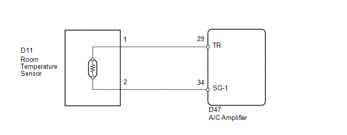
WIRING DIAGRAM
PROCEDURE
|
1. |
READ VALUE USING TECHSTREAM |
(a) Connect the Techstream to the DLC3.
(b) Turn the ignition switch to ON.
(c) Turn the Techstream on.
(d) Enter the following menus: Body / Air Conditioner / Data List.
(e) Check the value(s) by referring to the table below.
Air Conditioner|
Tester Display |
Measurement Item/Range |
Normal Condition |
Diagnostic Note |
|---|---|---|---|
|
Room Temperature Sensor |
Room temperature sensor / Min.: -6.5°C (20.3°F) Max.: 57.25°C (135.05°F) |
Actual cabin temperature displayed |
- |
OK:
The display is as specified in the Normal Condition column.
|
Result |
Proceed to |
|---|---|
|
NG |
A |
|
OK (When troubleshooting according to Problem Symptoms Table) |
B |
|
OK (When troubleshooting according to the DTC) |
C |
| B | .gif) |
PROCEED TO NEXT SUSPECTED AREA SHOWN IN PROBLEM SYMPTOMS TABLE |
| C | |
REPLACE A/C AMPLIFIER |
|
.gif)
|
2. |
INSPECT ROOM TEMPERATURE SENSOR |
(a) Remove the room temperature sensor.
(b) Disconnect the room temperature sensor connector.

(c) Measure the resistance according to the value(s) in the table below.
Standard Resistance:
|
Tester Connection |
Condition |
Specified Condition |
|---|---|---|
|
D11-1 - D11-2 |
10°C (50°F) |
3.00 to 3.73 kΩ |
|
D11-1 - D11-2 |
15°C (59°F) |
2.45 to 2.88 kΩ |
|
D11-1 - D11-2 |
20°C (68°F) |
1.95 to 2.30 kΩ |
|
D11-1 - D11-2 |
25°C (77°F) |
1.60 to 1.80 kΩ |
|
D11-1 - D11-2 |
30°C (86°F) |
1.28 to 1.47 kΩ |
|
D11-1 - D11-2 |
35°C (95°F) |
1.00 to 1.22 kΩ |
|
D11-1 - D11-2 |
40°C (104°F) |
0.80 to 1.00 kΩ |
|
D11-1 - D11-2 |
45°C (113°F) |
0.65 to 0.85 kΩ |
|
D11-1 - D11-2 |
50°C (122°F) |
0.50 to 0.70 kΩ |
|
D11-1 - D11-2 |
55°C (131°F) |
0.44 to 0.60 kΩ |
|
D11-1 - D11-2 |
60°C (140°F) |
0.36 to 0.50 kΩ |
NOTICE:
- Hold the sensor only by its connector. Touching the sensor may change the resistance value.
- When measuring, the sensor temperature must be the same as the ambient temperature.
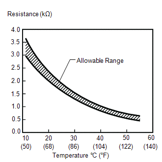
HINT:
As the temperature increases, the resistance decreases (see the graph).
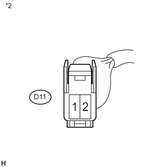
Text in Illustration|
*1 |
Component without harness connected (Room Temperature Sensor) |
|
*2 |
Sensing Portion |
| NG | |
REPLACE ROOM TEMPERATURE SENSOR |
|
|
3. |
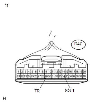
CHECK HARNESS AND CONNECTOR (ROOM TEMPERATURE SENSOR - A/C AMPLIFIER) |
|
(a) Disconnect the A/C amplifier connector. |
|
|
(b) Measure the resistance according to the value(s) in the table below. Standard Resistance:
|
|
| OK | |
REPLACE A/C AMPLIFIER |
| NG | |
REPAIR OR REPLACE HARNESS OR CONNECTOR |
 Compressor Lock Sensor Circuit (B1422/22)
SYSTEM DESCRIPTION
The ECM sends the engine speed signal to the A/C amplifier via CAN communication.
The A/C amplifier reads the difference between compressor speed and engine speed.
When the diff ...
 Ambient Temperature Sensor Circuit (B1412/12)
DESCRIPTION
The ambient temperature sensor is installed in front of the condenser. It detects
the ambient temperature to control air conditioning AUTO mode. This sensor is connected
to the A/C am ...
Other materials about Toyota Venza:
Rear Window Defogger System does not Operate
DESCRIPTION
When the rear window defogger switch on the air conditioning control assembly
is pressed, the operation signal is transmitted to the air conditioning amplifier
assembly through the LIN communication line. When the air conditioning amplifier
...
PIG Power Supply Voltage Malfunction (C1552)
DESCRIPTION
When a problem occurs in the power steering system, the power source relay circuit
is shut off to stop the power assist.
DTC No.
DTC Detection Condition
Trouble Area
C1552
PIG power s ...
Reassembly
REASSEMBLY
PROCEDURE
1. INSTALL FRONT BUMPER SIDE RETAINER LH
(a) Engage the claw and install the front bumper side retainer LH.
Text in Illustration
*1
Bolt
*2
S ...

0.1258