Toyota Venza: Components
COMPONENTS
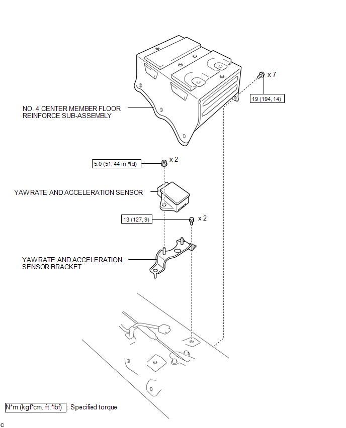
ILLUSTRATION
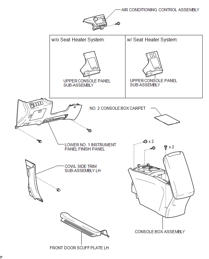
ILLUSTRATION
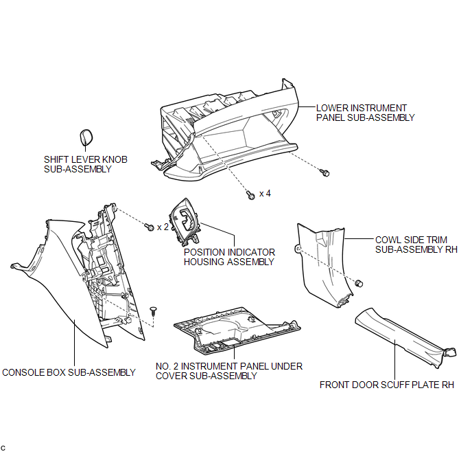
ILLUSTRATION

 Removal
REMOVAL
PROCEDURE
1. DISCONNECT CABLE FROM NEGATIVE BATTERY TERMINAL
CAUTION:
Wait at least 90 seconds after disconnecting the cable from the negative (-)
battery terminal to disable the SRS sys ...
Other materials about Toyota Venza:
System Diagram
SYSTEM DIAGRAM
Communication Table
Transmitting ECU (Transmitter)
Receiving ECU (Receiver)
Signal
Line
Certification ECU
(Smart key ECU assembly)
Main body ECU
(Driver side junc ...
Reassembly
REASSEMBLY
PROCEDURE
1. INSTALL COOLER DRYER
(a) Using pliers, install a new cooler dryer to the modulator.
(b) Apply sufficient compressor oil to the O-ring and fitting surfaces
of t ...
Components
COMPONENTS
ILLUSTRATION
ILLUSTRATION
ILLUSTRATION
ILLUSTRATION
ILLUSTRATION
ILLUSTRATION
...
© 2016-2026 Copyright www.tovenza.com

0.1162
0.1162