Toyota Venza: Removal
REMOVAL
PROCEDURE
1. DISCONNECT CABLE FROM NEGATIVE BATTERY TERMINAL
CAUTION:
Wait at least 90 seconds after disconnecting the cable from the negative (-) battery terminal to disable the SRS system.
NOTICE:
When disconnecting the cable, some systems need to be initialized after the cable
is reconnected (See page .gif) ).
).
2. REMOVE FRONT SEAT ASSEMBLY LH (for Manual Seat)
HINT:
Refer to the procedure up to Remove Front Seat Assembly (See page
).
3. REMOVE FRONT SEAT ASSEMBLY LH (for Power Seat)
HINT:
Refer to the procedure up to Remove Front Seat Assembly (See page
)
4. REMOVE FRONT SEAT ASSEMBLY RH (for Manual Seat)
HINT:
Perform the same procedure as the LH side.
5. REMOVE FRONT SEAT ASSEMBLY RH (for Power Seat)
HINT:
Perform the same procedure as the LH side.
6. REMOVE UPPER CONSOLE PANEL SUB-ASSEMBLY (w/o Seat Heater System)
7. REMOVE UPPER CONSOLE PANEL SUB-ASSEMBLY (w/ Seat Heater System)
8. REMOVE NO. 2 CONSOLE BOX CARPET
9. REMOVE CONSOLE BOX ASSEMBLY
10. REMOVE AIR CONDITIONING CONTROL ASSEMBLY
11. REMOVE FRONT DOOR SCUFF PLATE LH
12. REMOVE COWL SIDE TRIM SUB-ASSEMBLY LH
13. REMOVE LOWER NO. 1 INSTRUMENT PANEL FINISH PANEL
14. REMOVE FRONT DOOR SCUFF PLATE RH
15. REMOVE COWL SIDE TRIM SUB-ASSEMBLY RH
16. REMOVE NO. 2 INSTRUMENT PANEL UNDER COVER SUB-ASSEMBLY
17. REMOVE LOWER INSTRUMENT PANEL SUB-ASSEMBLY
18. REMOVE SHIFT LEVER KNOB SUB-ASSEMBLY
19. REMOVE POSITION INDICATOR HOUSING ASSEMBLY
20. REMOVE CONSOLE BOX SUB-ASSEMBLY
21. REMOVE NO. 4 CENTER MEMBER FLOOR REINFORCE SUB-ASSEMBLY
(a) Turn back the floor carpet.
|
(b) Remove the 7 bolts and No. 4 center member floor reinforce sub-assembly. |
|
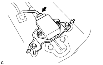
22. REMOVE YAW RATE AND ACCELERATION SENSOR
(a) Disconnect the connector from the yaw rate and acceleration sensor with bracket.
|
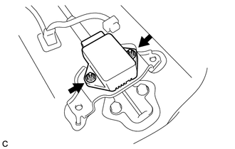
(b) Remove the 2 bolts and yaw rate and acceleration sensor with bracket. |
|
|
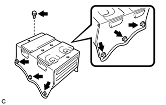
(c) Remove the 2 nuts and yaw rate and acceleration sensor from the bracket. |
|
 Components
COMPONENTS
ILLUSTRATION
ILLUSTRATION
ILLUSTRATION
...
 Installation
INSTALLATION
PROCEDURE
1. INSTALL YAW RATE AND ACCELERATION SENSOR
(a) Install the yaw rate and acceleration sensor to the bracket with
the 2 nuts.
Torque:
5.0 N·m {51 kgf·c ...
Other materials about Toyota Venza:
Transfer Case Rear Oil Seal
Components
COMPONENTS
ILLUSTRATION
ILLUSTRATION
Replacement
REPLACEMENT
PROCEDURE
1. REMOVE TAIL EXHAUST PIPE ASSEMBLY
2. REMOVE CENTER EXHAUST PIPE ASSEMBLY
3. REMOVE PROPELLER WITH CENTER BEARING SHAFT ASSEMBLY
4. REMOVE TRANSFER C ...
Installation
INSTALLATION
PROCEDURE
1. INSTALL FRONT SUSPENSION MEMBER BODY MOUNTING REAR CUSHION LH
(a) Temporarily install a new front suspension member body mounting rear
cushion LH while confirming the installation direction.
NOTICE:
Position th ...
Front Passenger Seat Belt Warning Light
Components
COMPONENTS
ILLUSTRATION
Installation
INSTALLATION
PROCEDURE
1. INSTALL ACCESSORY METER ASSEMBLY (w/o Rear View Monitor System)
(a) Connect the connector.
(b) Engage the 2 clamps.
(c) Engage the 2 clips.
(d) Install the accessory mete ...

0.1768