Toyota Venza: Correct driving posture
Drive with a good posture as follows:
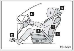
1. Sit upright and well back in the seat.
2. Adjust the position of the seat forward or backward to ensure the pedals can be reached and easily depressed to the extent required. 3. Adjust the seatback so that the controls are easily operable.
4. Adjust the tilt and telescopic positions of the steering wheel downward so the airbag is facing your chest.
5. Lock the head restraint in place with the center of the head restraint closest to the top of your ears. 6. Wear the seat belt correctly.
CAUTION
- While driving
• Do not adjust the position of the driver’s seat.
Doing so could cause the driver to lose control of the vehicle.
• Do not place a cushion between the driver or passenger and the seatback.
A cushion may prevent correct posture from being achieved, and reduce the effectiveness of the seat belt and head restraint, increasing the risk of death or serious injury to the driver or passenger.
• Do not place anything under the front seats.
Objects placed under the front seats may become jammed in the seat tracks and stop the seat from locking in place. This may lead to an accident.
The adjustment mechanism may also be damaged.
- Adjusting the seat position
• Do not recline the seat more than necessary when the vehicle is in motion, to reduce the risk of sliding under the lap belt.
If the seat is too reclined during an accident, the lap belt may slide past the hips and apply restraint forces directly to the abdomen or your neck may contact the shoulder belt, increasing the risk of death or serious injury.
• Take care when adjusting the seat position to ensure that other passengers are not injured by the moving seat.
• Do not put your hands under the seat or near the moving parts to avoid injury.
Fingers or hands may become jammed in the seat mechanism.

 SRS airbags
The SRS airbags inflate when the vehicle is subjected to certain types of
severe impacts that may cause significant injury to the occupants. They work together
with the seat belts to help reduce t ...
Other materials about Toyota Venza:
Components
COMPONENTS
ILLUSTRATION
ILLUSTRATION
ILLUSTRATION
ILLUSTRATION
ILLUSTRATION
...
How To Proceed With Troubleshooting
CAUTION / NOTICE / HINT
HINT:
Use the following procedure to troubleshoot the smart key system.
*: Use the Techstream.
PROCEDURE
1.
VEHICLE BROUGHT TO WORKSHOP
NEXT
...
Reverse Signal Circuit
DESCRIPTION
The radio and display receiver assembly receives a reverse signal from the park/neutral
position switch assembly.
WIRING DIAGRAM
PROCEDURE
1.
CHECK BACK-UP LIGHT
(a) Move the shift lever to R and check if th ...

0.1729