Toyota Venza: Components
COMPONENTS
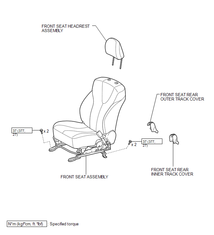
ILLUSTRATION
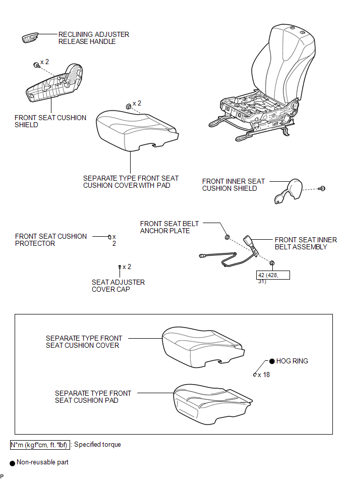
ILLUSTRATION
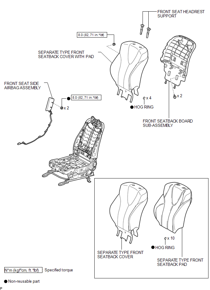
ILLUSTRATION
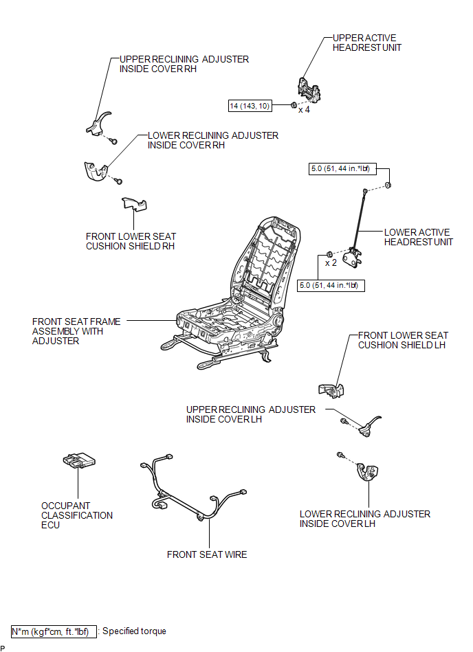
ILLUSTRATION

 Removal
REMOVAL
PROCEDURE
1. PRECAUTION
CAUTION:
Be sure to read Precaution thoroughly before servicing (See page
).
If the front seat side airbag assembly was deployed, replace the front ...
Other materials about Toyota Venza:
Lost Communication with "Door Control Module A" (U0199)
DESCRIPTION
DTC No.
DTC Detection Condition
Trouble Area
U0199
No communication from the outer mirror control ECU (for front passenger
side) continues.
Outer mirror control ...
Motor Rotation Angle Sensor Malfunction (C1528)
DESCRIPTION
The motor rotation angle sensor detects the motor rotation angle and sends this
information to the power steering ECU.
DTC No.
DTC Detection Condition
Trouble Area
C1528
Motor rotatio ...
System Too Lean (Bank 1) (P0171,P0172)
DESCRIPTION
The fuel trim is related to the feedback compensation value, not to the basic
injection duration. The fuel trim consists of both the short-term and long-term
fuel trims.
The short-term fuel trim is fuel compensation that is used to constantly ...

0.1147